SLVUC71 May 2021 TPS22992
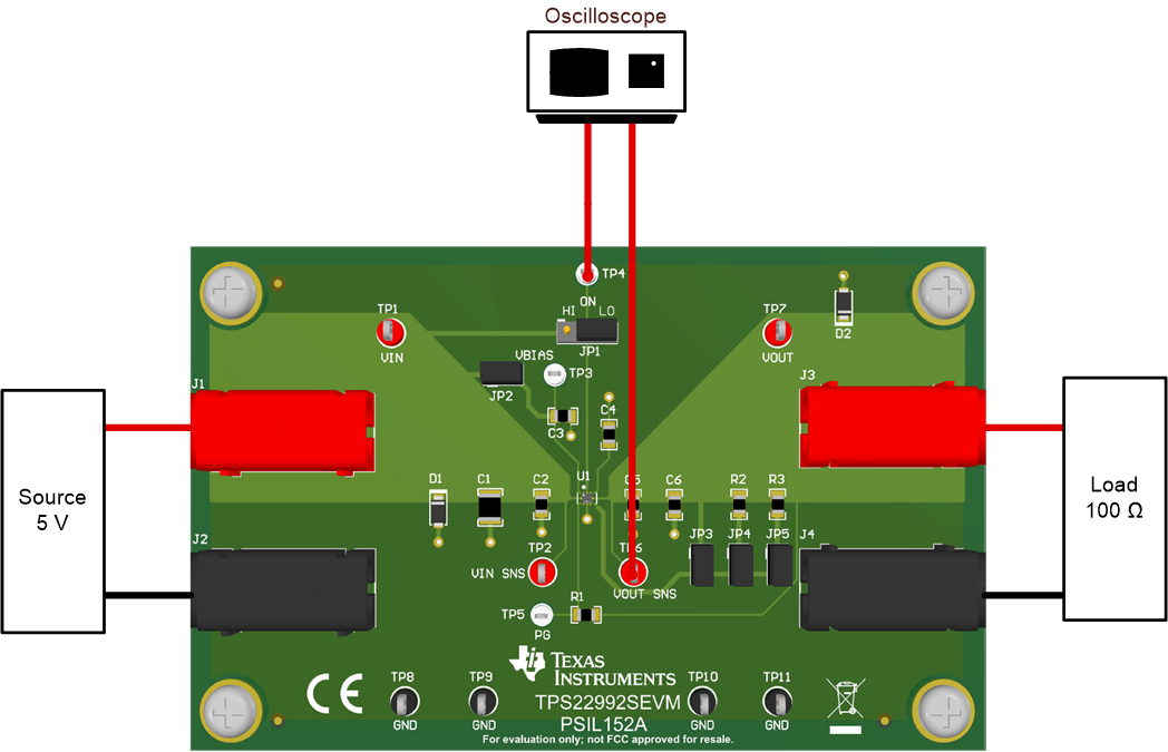
6.2 Rise Time Test Setup
Figure 5 shows the test setup for measuring the rise time of the TPS22992S. Apply a squarewave to the ON pin of the switch using a function generator and apply a voltage to the VIN terminal using a power supply. Observe the waveform at VOUT Sense with an oscilloscope to measure the slew rate and rise time of the switch with a given input voltage.
 Figure 6-2 Rise Time Test Setup