SLVUC77 June 2021 DRV8770
3.2 PWM Control with Potentiometers
After the power and motor have been connected properly as described in Section 3.1, The motor is ready to be driven.
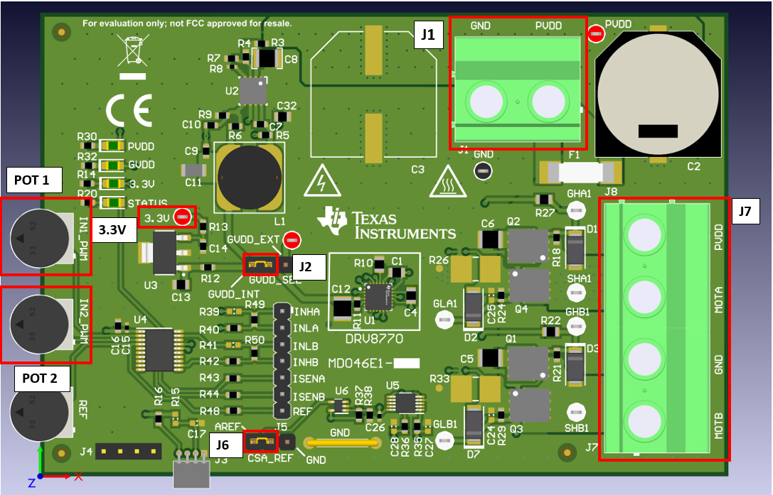
The INHx and INLx control signals are control by a fixed 20 kHz frequency with the duty cycle adjusted by potentiometer 1 (IN1_PWM) and potentiometer 2 (IN2_PWM). POT1 controls the duty cycle of INHA and INLA and POT2 the duty cycle of INHB and INLB. If the user wants to use an external PWM signal for INHx and INLx, R19, R50, R40, and R42 should be removed and the external signal connected to INHA, INLA, INHB, and INLB test points on J5.
Adjusting the duty cycle with POT1 and POT2 can be done by moving the potentiometer either clock-wise or counter-clockwise with in the board orientation shown in Figure 3-2. Moving the potentiometer counter-clockwise will decrease the duty cycle and clock-wise will increase the duty cycle.
There can be three possible motor configurations with the DRV8770. The control procedure is different for each configuration. The steps below explain how to control a motor or load dependig on the configuration:
- Motor or load is connected between MOTA and MOTB. Im this configuration, the motor is connected between both half bridges allowing for bi-directional control. This is the standard PWM control full bridge configuration with POT1 (INHA and INLA) controlling the duty cycle of MOTA and POT2 (INHB and INLB) controlling the duty cycle of MOTB. Adjusting the duty cycle of MOTA and MOTB will adjust the speed and direction of the motor.
- Motor or load is connected between either MOTA or MOTB and PVDD. This configuration allows for uni-directional control of the motor. POT1 controls MOTA and POT2 controls MOTB. If motor is connected between MOTA and PVDD for example, a LOWER INHA and INLA duty cycle will result in HIGHER motor speed and LOWER speed when the duty cycle is higher.
- Motor or load is connected between either MOTA or MOTB and GND. This configuration allows for uni-directional control of the motor. POT1 controls MOTA and POT2 controls MOTB. If motor is connected between MOTA and PVDD for example, a LOWER INHA and INLA duty cycle will result in LOWER motor speed and HIGHER speed when the duty cycle is higher.
 Figure 3-2 Detailed top 3D view of the
DRV8770EVM