SLVUCD2 January 2022 TPS65917-Q1
3.1 System Voltage Monitoring
| REGISTER | BIT | DESCRIPTION | OTP VALUE | UNIT | ||
|---|---|---|---|---|---|---|
| VSYS_MON | VSYS_HI | System voltage rising-edge threshold | 3.1 | V | ||
| VSYS_LO | VSYS_LO | System voltage falling-edge threshold | 2.75 | V | ||
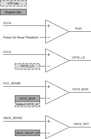
Comparators that monitor the voltage on the VCC_SENSE, and VCCA pins control the power state machine of the TPS65917-Q1 device. For electrical parameters, refer to the data sheet.
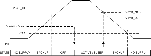
- PORWhen the supply at the VCCA pin is below the POR threshold, the TPS65917-Q1 device is in the NO SUPPLY state. All functionality is off. The device moves from the NO SUPPLY state to the BACKUP state when the voltage in VCCA rises above the POR threshold.
- VSYS_LOWhen the voltage on the VCCA pin rises above VSYS_LO, the device enters from the BACKUP state to the OFF state. When the device is in an ACTIVE, SLEEP, or OFF state and the voltage on VCCA decreases below the VSYS_LO level, the device enters backup mode. The level of VSYS_LO is OTP programmable.
- VSYS_MONDuring power up, the value of VSYS_HI OTP is used as a threshold for the VSYS_MON comparator which is gating PMIC start-up (that is, as a threshold for transition from the OFF state to the ACTIVE state). The VSYS_MON comparator monitors the VCC_SENSE pin. After power up, software can configure the comparator threshold in the VSYS_MON register.
- VBUS_DETThe VBUS_DET comparator is monitoring the VBUS_SENSE (secondary function of GPIO1) pin. This comparator is active when VCCA is greater than the POR threshold. Triggering the threshold level generates an interrupt. It can wake up the device from the SLEEP state, but can also switch on the device from the OFF state.
 Figure 3-1 PMIC Comparators
 Figure 3-2 State Transitions
The maximum input voltage of the VCC_SENSE pin depends on the OTP setting of PMU_CONFIG [HIGH_VCC_SENSE] as listed in the Recommended Operating Conditions table of the TPS65917-Q1 data sheet. This configuration is set as HIGH_VCC_SENSE = 0 with the VCC_SENSE and pins are connected to VCCA.
For the recommended operating conditions of the electrical parameters, see the TPS65917-Q1 data sheet, TPS65917-Q1 Power Management Unit (PMU) for Processor.