SLYU065 March 2023 TMAG6180-Q1 , TMAG6181-Q1
3.2.1.3.2 GUI Operation
To operate the GUI, follow these steps:
- Connect the EVM to TI-SCB and mount
the Roate & Push Module.
Figure 3-10 TMAG6180-6181EVM with Magnet Knob Attachment
- Connect to and launch the GUI as described in Section 3.2.1.3.1.
- With the EVM connected to the GUI,
close the README.md file page. The text near the bottom-left hand corner of the
GUI reads Hardware Connected (see Figure 3-11).
 Figure 3-11 Hardware Connected
Indicator
Figure 3-11 Hardware Connected
Indicator- If Hardware
Connected does not show in the bottom-left hand corner of the
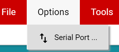
GUI, check different hardware COM ports under Options → Serial
Port (see Figure 3-12).
 Figure 3-12 Change Serial
Port
 - If the hardware still does not connect, make sure you are using the correct GUI/EVM combination.
- If Hardware
Connected does not show in the bottom-left hand corner of the
GUI, check different hardware COM ports under Options → Serial
Port (see Figure 3-12).
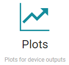
- Click on the Plots icon to setup
the EVM for measurements.
 Figure 3-13 Plots Page
Icon
 - Select the Sensor to test using the
drop-down menu shown in the figure below:
Figure 3-14 Device Select Drop-Down
- Click
Collect Data to initiate data capture.
Figure 3-15 Data Collection Settings
- Delay between samples setS the sample rate.
- #Samples sets the plot record length.
- #Samples Only stops collecting after the specified samples are captured, and disabling this checkbox causeS data to stream continuously.
- Observe the status indicators
relative to the device being tested:
- TMAG6180-Q1: Q0 and Q1
indicates the quadrant of rotation for the magnetic source. The quadrant
of rotation is also indicated by LEDs mounted on the EVM.
Figure 3-16 TMAG6180 Quadrature Output Indicators
- TMAG6181-Q1: Turns count
increments and decrements by 0.25 as each quadrant change occurs. The
PWM output is captured and converted for position tracking.
Figure 3-17 TMAG6181 Turns Indicator
- Additionally, the
PWM output can be probed directly using the Turns test
point.
Figure 3-18 TURNS Test Point Location
- Additionally, the
PWM output can be probed directly using the Turns test
point.
- TMAG6180-Q1: Q0 and Q1
indicates the quadrant of rotation for the magnetic source. The quadrant
of rotation is also indicated by LEDs mounted on the EVM.
- Click Stop Collect to stop
data capture.
Figure 3-19 Stop Data Collection
- Click Save Plot or Save
all Plots to store captured data locally.
Figure 3-20 Save Button