SLYY205A March 2021 – October 2022 TPS562211 , TPS562212 , TPS562231 , TPS563211 , TPS563212 , TPS563231 , TPS56339
PWM operation mode
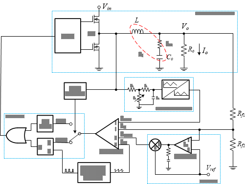
The PWM mode control scheme is similar to PCM control. As shown in Figure 10, the internal clock initials one on-pulse; the high-side FET then turns on, with current increasing in the inductor. When the emulated ramp voltage, feedback voltage and slope compensation voltage reach the integrated reference voltage, the high-side FET turns off and the low-side FET turns on until the next clock cycle. Therefore, in PWM mode, the switching frequency is truly fixed.
 Figure 9 AECM control block
diagram.
Figure 9 AECM control block
diagram.Figure 11 shows the load-transient behavior of the AECM device. The duty cycle increases or decreases with a decrease or increase of VOUT.