SLYY205A March 2021 – October 2022 TPS562211 , TPS562212 , TPS562231 , TPS563211 , TPS563212 , TPS563231 , TPS56339
Smart loop-bandwidth control
Unlike PCM control, where direct inductor current information is in the loop, AECM uses emulated inductor current information. The output filter of AECM control introduces one double pole like the D-CAP2 control topology. Thus, the Bode plot of AECM control is similar to the D-CAP2 control topology.
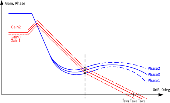
In D-CAP2 control, the Acp is constant and the DC gain of the open-loop transfer function changes with VOUT. While in AECM control, the Acp adapts to the changing value of R2 per the VOUT setting to keep the Acp × VOUT a constant value for a fixed DC gain. As shown in Figure 13, assuming that the double poles for different outputs are the same, the loop bandwidths under different outputs should be much closer to each other when compared to the loop bandwidths of D-CAP2 control.
 Figure 13 Bode plot under different
VOUT conditions of AECM.
Figure 13 Bode plot under different
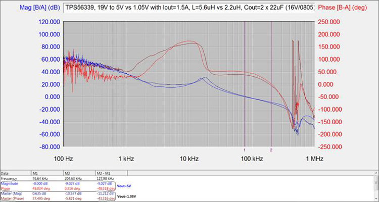
VOUT conditions of AECM.Figure 14 shows the measured Bode plot of AECM control under different VOUT conditions. The DC gains are almost the same. The crossing frequency and phase margin have slight differences because of the output double-pole shift.
 Figure 14 Measured Bode plot of 5-V and
1.05-V outputs.
Figure 14 Measured Bode plot of 5-V and
1.05-V outputs.| Traditional PCM Buck Converter (internal compensation) | AECM Buck Converter | |
|---|---|---|
| Load- transient response |
|
|
| Light load pulse |
|
|
| Wide output stability |
|
|
| D-CAP2 Buck Converter | AECM Buck Converter | |
|---|---|---|
| Frequency |
|
|
| High VOUT |
|
|
| Large duty cycle |
|
|