SNAA285 October 2015 LMK61E2
3
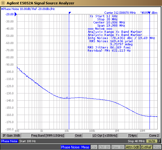
The impact of the jitter noise floor of the oscilloscope can also be seen in the random jitter measurement result (RJ). The filtered RJ from Figure 1 is ~287fs. A low pass filter of 20 MHz was applied for this measurement. Since the acquisition interval was set to 40us, effect of noise frequencies down to 1/40us = 25 kHz are included in the measurement. In contrast, the integrated RMS phase jitter (12 kHz – 20 MHz) measured using the Agilent 5052 Phase Noise Analyzer (superior noise floor when compared to real-time oscilloscopes) is ~87fs (as shown in Figure 3). Filtered RJ in time-domain is equivalent to the Integrated RMS phase jitter in frequency domain.
 Figure 3. LMK61E2 312.5 MHz Phase Noise
 In summary, when performing jitter measurements in time-domain using real time oscilloscopes from different oscilloscope vendors, it is important to consider all the sources of jitter that are intrinsic to the oscilloscope. The impact of some of these errors can be minimized by careful action on part of the operator. Ensuring fast slew rate for the signal being measured, use of the highest sampling rate available on the oscilloscope for the measurement, setting the input signal amplitude to full scale and use of sinc interpolation or enhanced bandwidth setting (if available) on the oscilloscope are some of the steps that the operator can follow to minimize the sources of error in the jitter measurement. The oscilloscope with the lowest jitter noise floor will represent the true jitter of the input signal most accurately.