SNAA360 June 2022 ADC32RF54 , ADC32RF55 , AFE7950 , LMX1204
2.2 Cascaded Device Performance
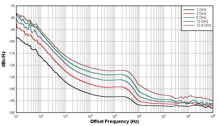
Figure 2-2 shows phase noise performance using the same R&S SMA100B RF signal generator driving the Figure 1-2. The following data showcases device performance at the same frequencies as the previous section: 1 GHz, 3 GHz, 6 GHz, 10 GHz, and 12.8 GHz.
 Figure 2-2 Cascaded LMX1204 Phase Noise
Measurements
Figure 2-2 Cascaded LMX1204 Phase Noise
MeasurementsThe +12 V supplying the cascaded LMX1204 design is generated by the R&S FSWP26 phase noise analyzer. All five LMX1204 devices are programmed for bypass mode with maximum output power.