SNAK020 January 2024 LMX1906-SP
PRODUCTION DATA
2 Test Method
The devices under test (DUTs) were put through a 240-hour burn-in with the units biased and operational at 125°C ambient prior to the radiation testing.
Irradiation and electrical testing were done at Texas Instruments Radiation Test Facility in Santa Clara, California.
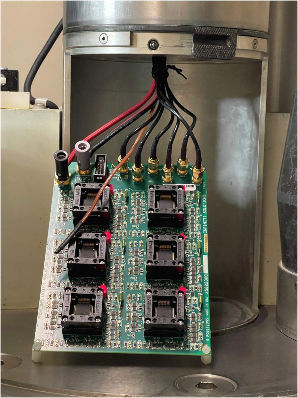
The DUTs were placed in socketed bias boards (as shown in Figure 2-1), powered up, irradiated and electrically tested at 0, 30, 50, and 100krad (Si). All specified data sheet and SMD parameters were tested. In addition to the specified parameters, the test program tests many other parameters to verify the proper operation of the device. Limits are set using a six sigma baseline.
 Figure 2-1 LMX1906-SP TID Bias Board
Table 2-1 RLAT Conditions
| Wafer lot | 2013693 |
| Number samples tested | 6 |
| DUT serial numbers | 163-168 |
| Test location | Texas Instruments, Santa Clara, CA |
| Bias board schematic | 356SCH23 |
| Bias board edge number | 6647792 |
| Supply voltage | 2.5V |
| Supply current | 1.4A per unit |
| Input frequency | 800MHz |
| Output frequency | 3200MHz |
| Test programs | GQR1906AA |
| Electrical test supply voltage | 2.5V |
| Dose Rate | 23.8rad/s |
| Test points | 0, 30, 50, 100krad (Si) |
| Test dates | Dec. 11, 2023 |