SNAU267A June 2021 – June 2021 HDC3020 , HDC3021 , HDC3022
5.2 Data Capture Tab
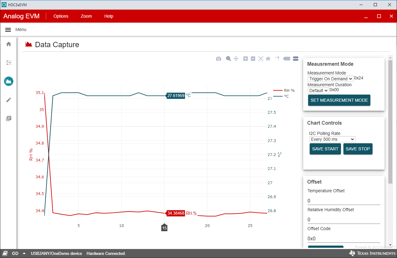
The Data Capture tab reports the temperature and humidity from the HDC3020 device included on the HDC3020EVM. Each selection option/button on this tab has a specific function as described below:
- Measurement Mode tab
- Measurement mode: Can select Trigger-On Demand (one-shot mode) or the Auto Measurement mode with the appropriate frequency
- Measurement duration: Changes the number of measurement bits for humidity/temperature measurements
- Chart Controls
- I2C polling rate: Changes the communication frequency between the MCU and the HDC3020EVM
- Offset
- Temperature Offset: Offsets the temperature value and sets it within the HDC3020 device
- Humidity Offset: Offsets the humidity value and sets it within the HDC3020 device
- Status
- Read Status: Reads the information about the operating state of the HDC3020
- Clear Status: Clears the contents stored in the status registers
- Alert
- Temperature Limit: Reads/writes the temperature threshold
- Humidity Limit: Reads/writes the humidity threshold
- Limit Code: Hex code representing the truncated 16-bit threshold value
- Other
- Software reset: Issues a software reset
- Enable Heater: Heating element included in device to remove any condensation on the device
- Disable Heater: Disables the heater
- NIST ID
- Read NIST ID: Returns the unique 48-bit value of the HDC3020.
 Figure 5-2 HDC3020EVM GUI Data Capture
Tab
Figure 5-2 HDC3020EVM GUI Data Capture
Tab- Drift
Correction
- The Drift Correction Algorithm calibrates the device and corrects any observed sensor drift that may be encountered due to device mishandling or exposure to contaminants. This feature is not supported in Auto Measurement Mode and the device can only support this algorithm if the drift is less than 25% RH. If the observed drift after running this algorithm is greater than 25%, then the error is only reduced by (actual drift - 25%)
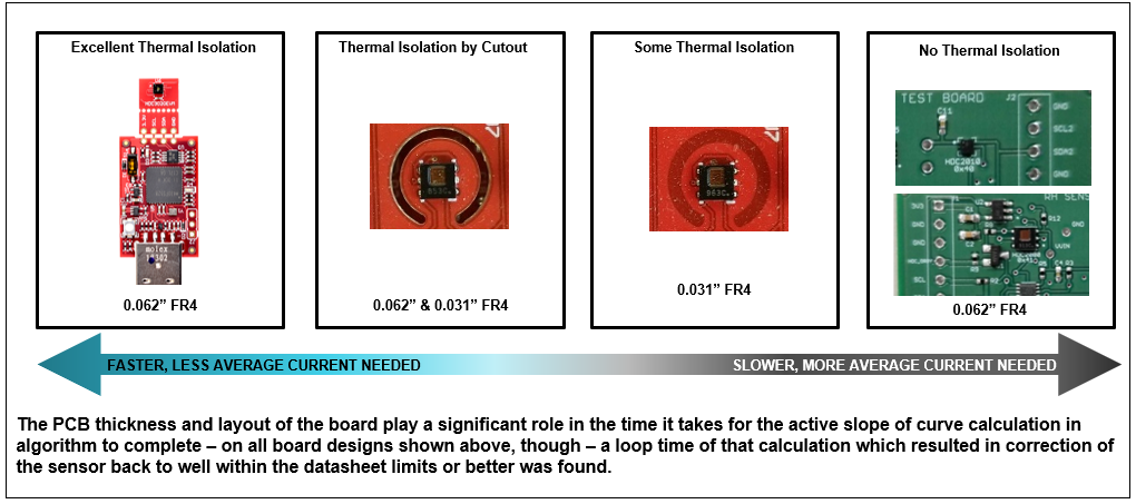
- Figure 5-3 describes the different layout considerations that can be implemented on the HDC devices. The EVM and the layout with the cutout would require lower current to execute the Drift Correction Algorithm. However, the layout that has little to no thermal isolation would require a lot more current to execute this command. The HDC3020EVM GUI offers three different power levels to run this algorithm: Min Power, Mid Power and Max Power
 Figure 5-3 Thermal Isolation
Examples
Figure 5-3 Thermal Isolation
Examples- This feature is currently only available for a demonstration purpose on the HDC3020EVM. The power settings are specifically chosen to correct the drift on the HDC3020EVM and code compensates for this layout.
Note:The Max power should only be used when there is no thermal isolation on the PCB. Using this setting for more than 5 minutes can damage the sensor.
- Execute: This command
executes the Drift Correction Algorithm
- After running this algorithm, the drift offset is displayed in the offset register tab (as shown in figure 5-4). To correct the offset, select the Write Offset command and the RH value is corrected.
- The execution time depends on the power setting and the drift observed, but should not last more than 5 minutes. If the algorithm is taking a lot of time, abort the execution and re-start after a few minutes.
 Figure 5-4 Offset Register
Displaying the HDC3020 Drift Offset
Figure 5-4 Offset Register
Displaying the HDC3020 Drift Offset- Abort: Aborts the drift Correction in the middle of an execution.