SNLA236 September 2015 DS125BR111 , DS125BR401A , DS125BR820
3 Equalizer Placement within a SAS-3 Channel
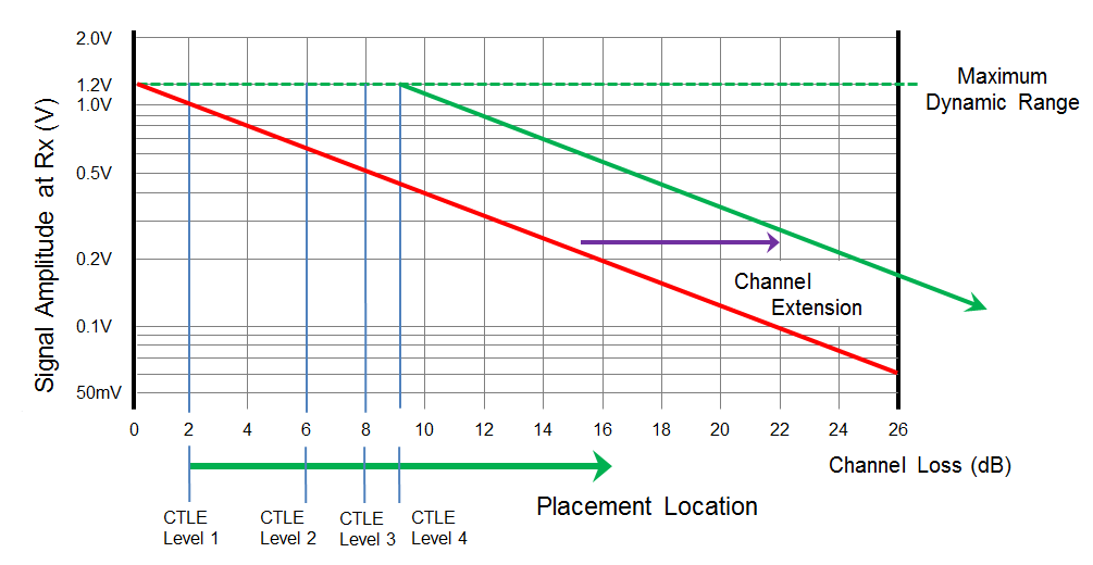
The benefits of a linear equalizer can only be realized if it is placed some distance away from the SAS-3 transmitter. The physical distance may vary based on materials used in PCB fabrication, but not the attenuation. Since linear equalizers compensate for PCB or cable based attenuation, some attenuation must occur prior to the equalizer to result in any benefit. Figure 5 helps to show the minimum input loss required to optimize the possible channel extension. As the level of equalization in the DS125BR820 is increased, the device must be placed further away from the transmit source. Using an equalization setting which can drive the DS125BR820 beyond the 1.2 V dynamic range will result in non-linear operation. This will degrade the waveform and result in sub-optimal link training results.
Placement to maximize channel extension is not limited to a location roughly 10 dB removed from the transmit source. It is possible to achieve full extension when the DS125BR820 is placed at any point beyond the 10 dB minimum. If placement closer than 10 dB from the transmitter is required, a lower level of equalization is recommended.
 Figure 5. Illustration of Channel Extension and DS125BR820 Placement
 Table 3. DS125BR820 Settings Used for Testing
| EQ SETTING | OUTPUT SETTINGS | COMMENTS | |||
|---|---|---|---|---|---|
| VALUE | PIN STRAP | EQUIVALENT REGISTER SETTING | VOD | VOD_DB | |
| Level 1 | 0: 1 kΩ to GND | 0x2C or 0x00 | Level 2 - Level 6
or 0xAA – 0xAE |
0 dB
or 000’b |
Different EQ settings used for different input channel length. |
| Level 2 | R: 20 kΩ to GND | 0x2D or 0x01 | |||
| Level 3 | F: Floating | 0x2E or 0x02 | |||
| Level 4 | 1: 1 kΩ to VIH | 0x2F or 0x03 | |||
NOTE
Each channel has its own EQ, VOD, and VOD_DB control register.