SNLA236 September 2015 DS125BR111 , DS125BR401A , DS125BR820
5 Passing Out Of Band (OOB) Signals
Out of Band (OOB) Signaling is used in SATA and SAS to enable device-to-device communication and negotiation in a storage environment. This signaling uses a series of Idle and Active periods with specific timing. Any impact to this timing could cause major problems within a storage system. This makes undistorted propagation of the OOB signaling extremely important to a storage system design engineer.
Highlighting some key OOB signaling specifications from SATA3.1 gives some guidelines for the type of OOB and signal noise which could be encountered in a real storage system.
Table 5. OOB Specifications
| PARAMETER | UNITS | LIMIT | ELECTRICAL SPECIFICATION | ||
|---|---|---|---|---|---|
| Gen 1 | Gen 2 | Gen 3 | |||
| VTHRESH: OOB Signal Detection Threshold | mVppd | Min | 50 | 75 | 75 |
| Nom | 100 | 125 | 125 | ||
| Max | 200 | 200 | 200 | ||
| COMINIT/COMRESET and COMWAKE Transmit Burst Length | ns | Min | 103.5 | ||
| Nom | 106.7 | ||||
| Max | 109.9 | ||||
| COMINIT/COMRESET Transmit Gap Length | ns | Min | 310.4 | ||
| Nom | 320.0 | ||||
| Max | 329.6 | ||||
| COMWAKE Transmit Gap Length | ns | Min | 103.5 | ||
| Nom | 106.7 | ||||
| Max | 109.9 | ||||
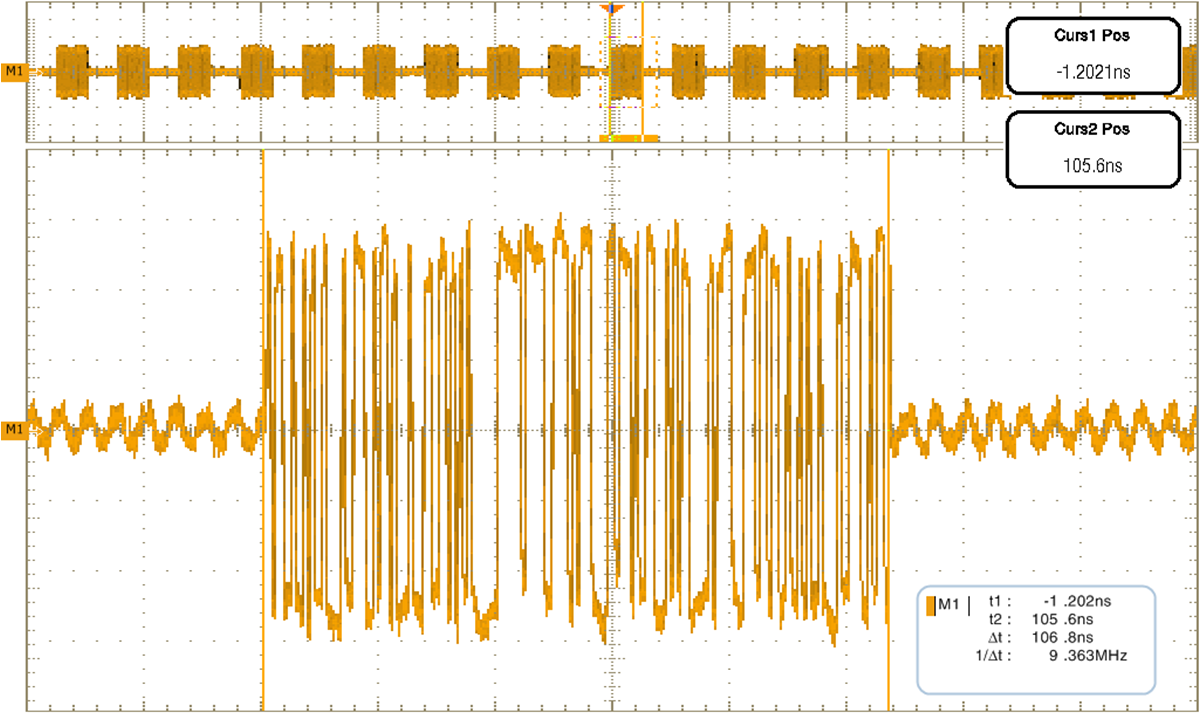
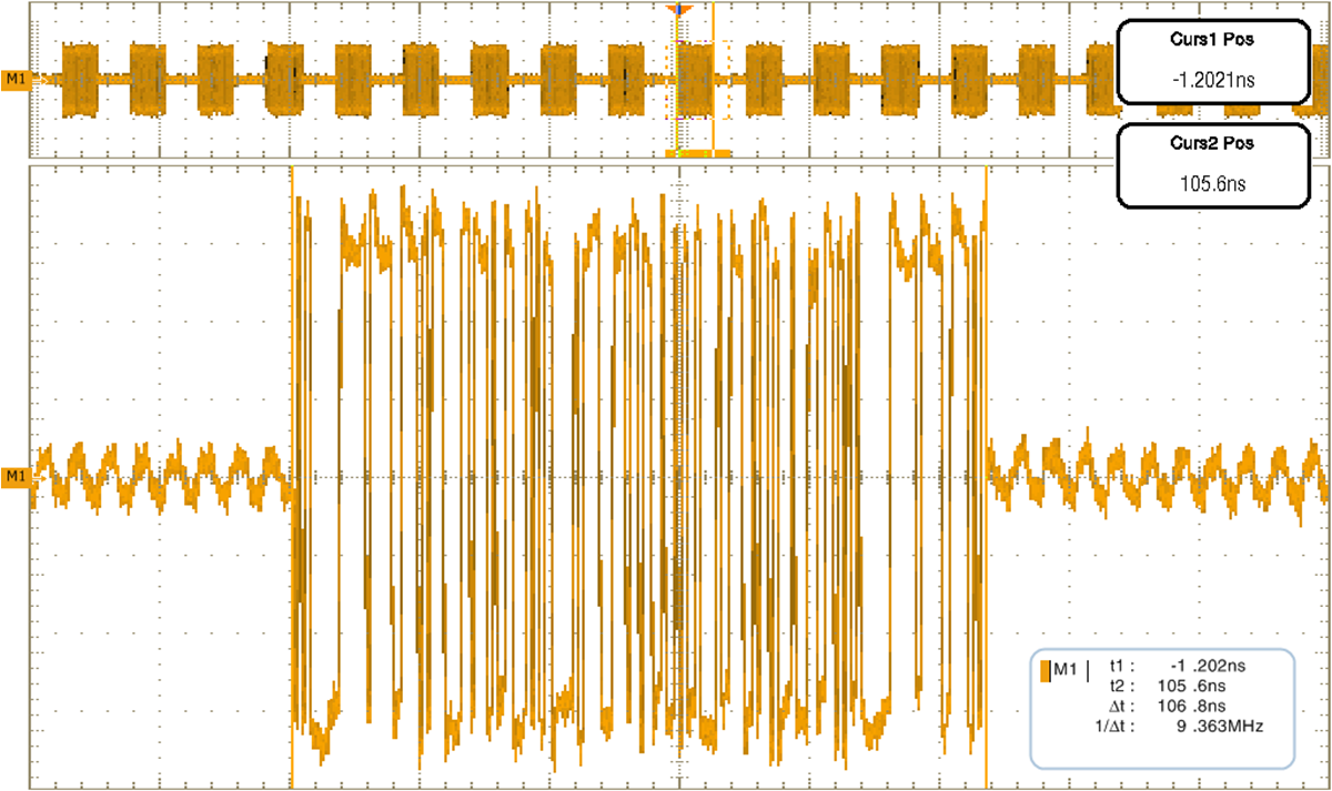
Using the COMWAKE waveform burst timing and a noise level equal to the typical OOB signal detection threshold represents a very difficult problem for most re-driver components. With a fully linear datapath, the DS125BR820 overcomes any distortion issues while propagating this waveform across SAS/SATA links ensuring robust OOB communication.
The visible noise injected in Figure 11 is 100 mVpp in amplitude at a frequency of 200 MHz.
 Figure 11. OOB Signaling at DS125BR820 Input
  Figure 12. OOB Signaling at DS125BR820 Output