SNLA299 August 2018 LMH0324 , LMH0397 , LMH1208 , LMH1218 , LMH1219 , LMH1297
-
LMH12xx MADI Compatibility Application Note
- Trademarks
- 1 MADI Specification Requirements
- 2
LMH12xx Device Family
- 2.1 LMH12xx Device Family
- 2.2 LMH1218 Device Family Hardware Changes to Support MADI Compatibility
- 2.3 LMH1219 Device Family Recommended Register Settings
- 3 Summary
- 4 References
2.1.3 LMH1297 Device Family Hardware Changes for MADI Compatibility
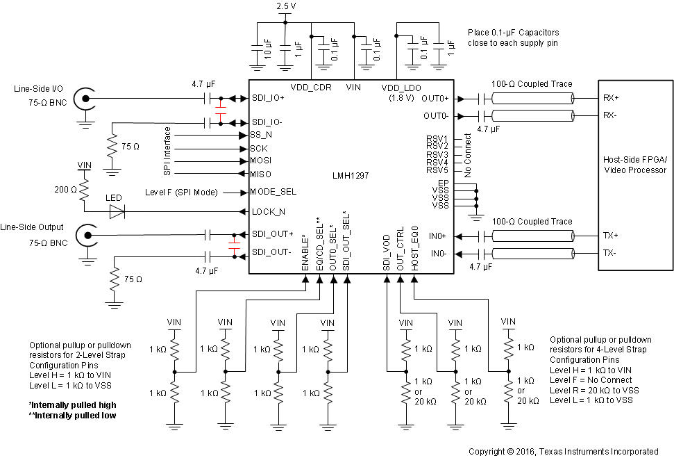
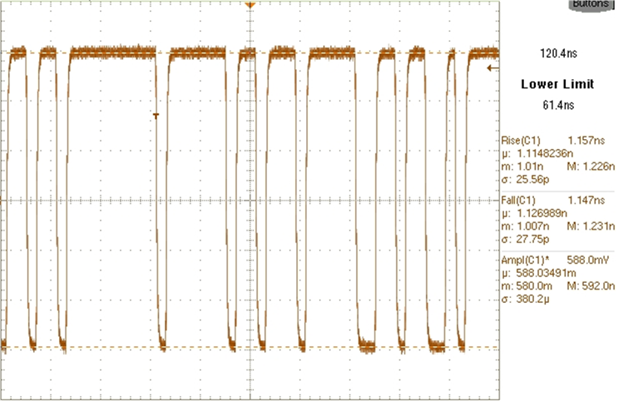
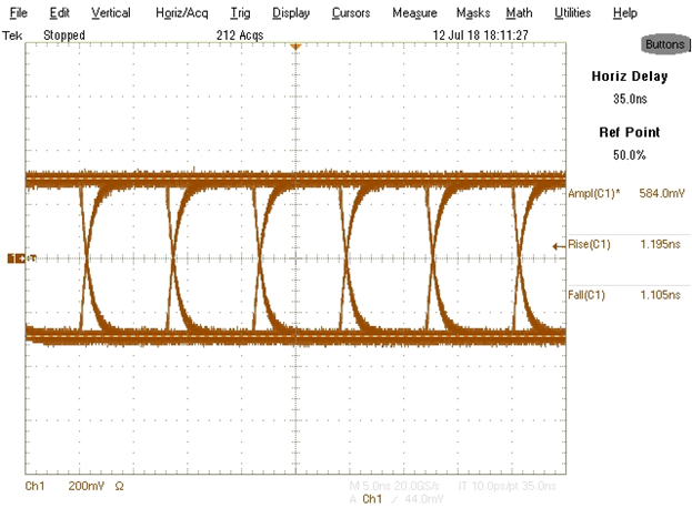
The LMH1297 device family meets SMPTE SDI slew rates. MADI requires 80%/20% rise/fall time to be within 1 nS to 3 nS. To meet this requirement, a 10-pF capacitor was added across SDI_OUT± or SDI_IO± as shown in Figure 5.
 Figure 5. LMH1297 Family Application Schematic
  Figure 6. LMH1297/LMH0397 MADI-Compatible Transmit Waveform
  Figure 7. LMH1297/LMH0397 MADI-Compatible Output Eye Diagram