SNLU288 December 2020
- Trademarks
- 1Introduction
-
2Description
- 2.1 DS160PR412 and DS160PR421 4-Level I/O Control Inputs
- 2.2 DS160PR412 and DS160PR421 Modes of Operation
- 2.3 DS160PR412 and DS160PR421 SMBus or I2C Register Control Interface
- 2.4 DS160PR412 and DS160PR421 Equalization Control
- 2.5 DS160PR412 and DS160PR421 RX Detect State Machine
- 2.6 DS160PR412 and DS160PR421 DC Gain Control
- 2.7 DS160PR412-421EVM Global Controls
- 2.8 DS160PR412-421EVM Downstream Devices Control
- 2.9 DS160PR412-421EVM Upstream Devices Control
- 2.10 Quick-Start Guide (Pin Mode)
- 2.11 Quick-Start Guide (SMBus Slave Mode)
- 3Schematics
- 4PCB Layouts
- 5Bill of Materials
2.11 Quick-Start Guide (SMBus Slave Mode)
- Configure all devices to operate in the SMBus Slave Mode by setting their MODE pins to the L1 level. This is accomplished by placing a shunt across pins 15–16 on JMP1, JMP2, JMP11, and JMP14 .
- Set a unique SMBus Slave address for each device by placing shunts in the following arrangement:
- On JMP1 connector, place shunt across pins 1-2 L0, downstream device PR412_0.
- On JMP2 connector, place a shunt across pins 3-4 L1 for downstream device PR412_1.
- On JMP11 connector, place a shunt across pins 5-6 L2 for upstream device PR421_2.
- On JMP14 connector, remove shunts across 1-2, 3-4, 5-6 so EQ0_ADD# pin is floating L3 for upstream device PR421_3.
- On JMP3-6, JMP9, JMP10, JMP15, and JMP16 move shuts from current position and install across pins 7-8.
- Enable all devices by pulling their PD pins to GND. This is accomplished by placing a shunt on JMP8 across pins 2-3.
- Connect USB2ANY Adapter to P4 (Note that the USB2ANY Adapter is not supplied with the DS160PR412-421EVM). Install shunt on JMP17 across pins 1-2.
- Install SigCon Architect Version 3.0.0.15 application and the DS160PR412-421 profile.
- Plug the EVM into a PCIe x16 server motherboard slot. Ensure the motherboard is powered down before installing the EVM or configured for hot-plug operation.
- Install a compatible PCIe endpoint card into the straddle connector of the EVM.
- Power-up the motherboard.
- Start the SigCon Architect application.
- Select the DS160PR412-421 Configuration Page and select the Apply box to enable the device profile. If necessary, edit device addresses in the Edit Device Addresses box.
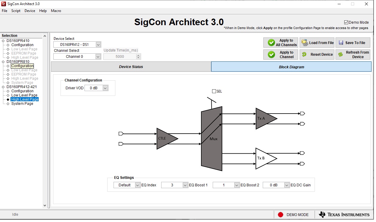
- In the DS160PR412-421 High Level Page, select Block Diagram as shown in Figure 2-1.
- Select desired EQ Settings and Driver VOD.
- Select the devices to which you want to apply the selected settings and click the Apply to All Channels button.
 Figure 2-1 SigCon Architect DS160PR412-421 High Level Page