SNOA952 May 2016 FDC2112 , FDC2112-Q1 , FDC2114 , FDC2114-Q1 , FDC2212 , FDC2212-Q1 , FDC2214 , FDC2214-Q1
2 Mathematical Modeling
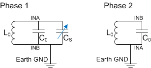
The reason for this ground shift phenomenon is explained by looking at the capacitance models of the system. Figure 1 shows a simple diagram of the FDC2214 and its capacitances. In this model, both the sensor and the system are referenced to earth ground where:
- C0 is the tank capacitance
- Cs is the sensor capacitance
- L0 is the tank inductance
The oscillator signal alternates between INA and INB, so the circuit configuration is different for each half cycle of the oscillation.
 Figure 1. Simplified Model of the FDC2214 EVM Board Referenced to Earth Ground Without a Large Local Ground Plane
 Use Equation 1, Equation 2, and Equation 3 for this configuration:
In Phase 1:

In Phase 2:

The effective oscillation frequency is the average of the two phases:

These equations show that if the entire system is referenced to earth ground, because L0 and C0 are fixed, the sensor frequency is only affected by variations in Cs, as intended.
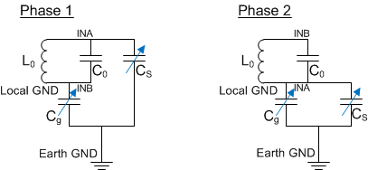
A second possible ground configuration is represented by a system that is not referenced to earth ground, but instead is isolated and uses a local ground. This is shown in Figure 2, where:
- Cg is the parasitic capacitance between local and earth ground
 Figure 2. Simplified Model of the FDC2214 EVM Board Floating Without a Large Local Ground Plane
 Figure 2 shows how the LC resonator interfaces with earth ground through the parasitic and sensor capacitances of Cs and Cg. In addition to the desired sensor capacitance, Cs, the secondary capacitance, Cg, acts as a sensor also, and is affected by the same objects that interact with the intended sensor, Cs.
Because no other branch bridges the circuit with earth ground in either phase of the half-sine wave excitation, Cs and Cg are effectively in series when referenced to local ground. This series relationship is given by Cx characterized by Equation 4:

where:

This additional Cg creates the above β factor which reworks the equations to the following:


In order for these equations to match those that characterize the ideal scenario of Figure 1, β should be as close to 1 as possible which means that Cg should be as large as possible. When the entire system is referenced to earth ground, Cg is theoretically infinite which forces β to be 1 and explains why the ground shift phenomenon is not observed. On the other hand, if Cg is not large enough, β will not be equal to 1 and will cause a shift in the frequency, which appears as a ground shift.
The next sections of this applications note will examine several possible ground configurations. To support the discussion, the reference system will be the FDC2214 EVM connected to a laptop through a USB cable.