SNOAA76 August 2021 LDC3114 , LDC3114-Q1
5 Observed Effects of Ambient Temperature
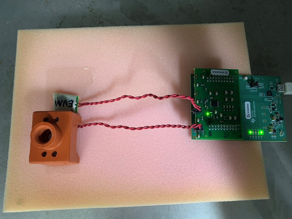
The variation of inductance and RP over temperature can result in measurement variations, a concept that is further explored in the Temperature Compensation application report. To observe this change with the setup that was previously characterized (see Section 4), a fixed distance was set between the copper target and the LDC3114EVM sensor coil. In addition to the coil and target, a reference coil was placed on Channel 1 of the EVM. Systems that are expected to operate over a set temperature range may need to calibrate the sensors accordingly. This dual sensor prototyping setup illustrated in Figure 5-1 can be used to observe the behavior of both sensors with a controlled environment and with a stationary target.
The copper target was secured in place over the Channel 0 sensor coil with rubber housing, to ensure that the target placement would not be affected by the chamber fan controls.
 Figure 5-1 LDC3114EVM Temperature Chamber
Setup
Figure 5-1 LDC3114EVM Temperature Chamber
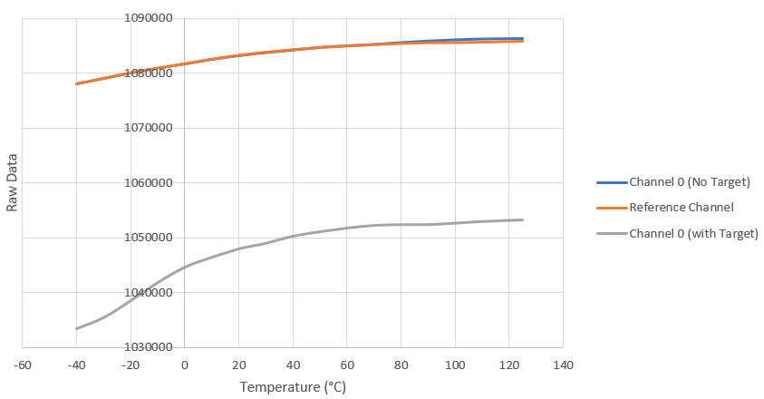
SetupFigure 5-2 illustrates the change in raw data across the operating temperature of the LDC3114. The raw data was collected and averaged across temperatures of –40°C to 125°C. This temperature range was chosen because it aligns with the recommended ambient operating temperature listed in the LDC3114 data sheet. The behavior of both the Channel 0 and Channel 1 sensors was first observed without any metal target present. Once it was confirmed that both sensors had the same response to the temperature sweep, a copper target was added to Channel 0.
 Figure 5-2 Observed Effect of Ambient
Temperature on LDC3114 With LDC3114EVM Coil
Figure 5-2 Observed Effect of Ambient
Temperature on LDC3114 With LDC3114EVM CoilThe resistance of a typical PCB coil increases as a function of temperature, mainly dependent on the resistivity of the metal. For a copper coil, the resistive temperature coefficient is 3900 ppm/°C. Additionally, the proportionality of RP to inductance means that as the RP value changes over temperature, so will the inductance.
Measurement drifts due to temperature can be corrected if the operating temperature range is known and the system behavior has been characterized. A reference coil that is not exposed to any varying target parameters can be placed in the same environment as the main sensor, and the reference sensor output can be used to calibrate the system for a specific temperature range.