SNOAA76 August 2021 LDC3114 , LDC3114-Q1
2.2 Sensing Distance
For inductive technology, 1 µm to 10 cm is a feasible sensing range. If an application requires high precision, a sensing range that is 50% of the coil diameter can be expected from most of the LDC devices. For example, a sensor with an outer diameter of 10 mm can be expected to have a sensing range of 5 mm. This range can be increased to 100% in low precision applications, such as a simple detection of metal presence.
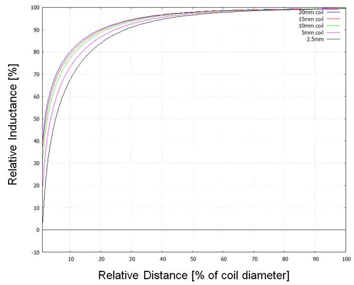
It is important to note that sensitivity is greatest within 20% of the total sensing distance, and this should be considered when designing a system based on maximum required sensing distance.
Figure 2-2 illustrates the relative inductance shift versus distance and it can be seen that within 20% of the coil diameter, the shifts in inductance are stronger with respect to smaller distances. This allows for higher precision measurements, for example, an application with a sensor diameter of 10 mm could provide nanometer resolution within a target distance of 2 mm.
 Figure 2-2 Relative Inductance vs Distance of
Various Coil Sizes