SNOU143 February 2017 EMB1428Q , EMB1499Q
4.1.2 Host Interface
The 6-pin J3 - Serial connector is used to connect the bq76PL455EVM to a PC running the GUI or to a host controller. Signals at the J3 - Serial connector are 5-V TTL signals. Texas Instruments recommends using FTDI’s USB-to-TTL serial converter cable to allow connection with a PC’s USB port. The recommended cable is available from FTDI (http://www.ftdichip.com), and the appropriate part number for the 1.8-meter cable is TTL-232R-5V.
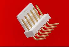
 Figure 3. Molex 22-12-4062 (Reference Image Only)
 Table 3. Connector Information
| Designator | Manufacturer | Part Number | Mating Connector |
|---|---|---|---|
| J3 | Molex | Manufacturer: 22-12-4062 | Manufacturer: 22-01-2061
Digi-Key: WM1579-ND Contacts: Manufacturer: 08-55-0101 (22-30 AWG) Digi-Key: WM2312CT-ND |
Table 4. Pin Description
 |
||
| Pin | Name | Mating Cable Color |
| 1 | Ground | Black |
| 2 | FAULT signal from bq76PL455A-Q1 | Black |
| 3 | 5-V input from PC | Red |
| 4 | RX from PC to bq76PL455A-Q1 | Orange |
| 5 | TX from bq76PL455A-Q1 to PC | Yellow |
| 6 | WAKE signal from PC | Green |