SNOU195 july 2023 LDC5072-Q1
- 1
- Abstract
- Trademarks
- 1 Introduction
- 2 Gaining Access to the LDC5072 Sensor Design Tool
- 3 Installer Setup
- 4 Installing the Tool
- 5 Tool Overview
- 6 Using the Tool to Create a Design and Generate a Supporting SPICE Model and Gerber Files
- 7 Running Simulations in Pspice
- 8 Layout, Bill-of-Materials, and Schematic of the Test PC board
- 9 Troubleshooting
- 10Revision History
6 Using the Tool to Create a Design and Generate a Supporting SPICE Model and Gerber Files
Upon starting the tool, the Log window is empty and the Valid Design indicator is red as shown in Figure 6-1.
 Figure 6-1 LDC5072 Sensor Designer Tool
Start Panel
Figure 6-1 LDC5072 Sensor Designer Tool
Start PanelThe example illustrated here assumes the parameters across all of the tabs stay at the default values. Note the parameters Max Velocity and Max Acceleration on the right side of the front panel, and which impacts Spice simulations. In simulations, the Max Acceleration controls the speed-up from zero to Max Velocity. If the acceleration is set to zero, then the target starts and operates at Max Velocity, which is recommended for short run times. If Max Acceleration is non-zero, the target starts at zero rotational speed and accelerates to Max Velocity, then deccelerates back to zero velocity. This can result in very long run times. The Temperature parameter sets the ambient temperature of the Spice simulation.
The Spice model can be made to include tolerances from the LDC5072 data sheet via the LDC5072 Tolerances tabs. The table in the Sensor Parameters tab provides summary tables of the mutual inductances and resistance, as well as the sensor coefficients of capacitance and inductance as calculated by the optimizer.
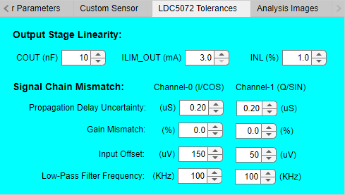 Figure 6-2 LDC5072 Sensor Designer
Tolerances Tab
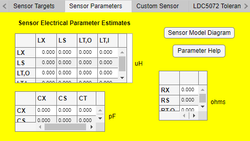 Figure 6-3 LDC5072 Sensor Designer
Sensor Parameters Tab
Figure 6-3 LDC5072 Sensor Designer
Sensor Parameters TabA schematic representation of the sensor Spice model can be seen by clicking the Sensor Model Diagram button on the Sensor Parameters tab. An explanation of the sensor electrical parameters can be seen by clicking the Parameter Help button.
 Figure 6-4 Schematic Representation of
the Sensor Spice Model
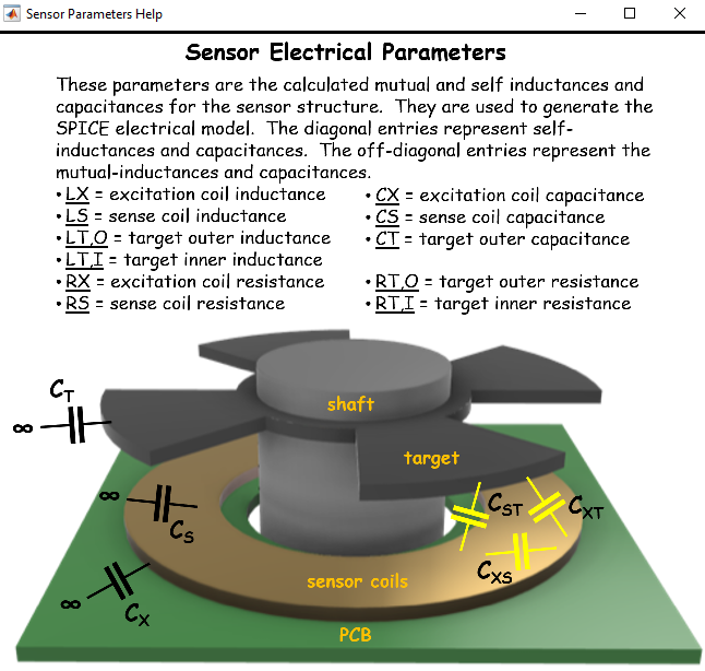 Figure 6-5 Parameter Help Pop-up
for the Sensor Spice Model
Figure 6-5 Parameter Help Pop-up
for the Sensor Spice ModelClicking the Design Sensor button starts the tool optimizer, with Log window entries scrolling through different status messages as the design progresses. When the design is complete, the Valid Design indicator turns green and the Log window displays "....completed design process." as shown in the figure below.
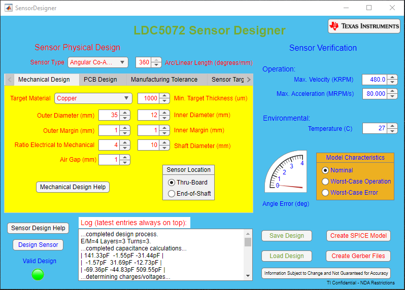 Figure 6-6 LDC5072 Sensor Designer Front
Panel: Completion of a Valid Design
Figure 6-6 LDC5072 Sensor Designer Front
Panel: Completion of a Valid DesignSome of the physical characteristics of the sensor designed by the tool's optimizer can be varied. After the optimizer produces a design, click the Import button on the Custom Sensor tab shown in the figure below to import the physical characteristics. Adjustments to the optimizer-created design can now be made. When the box Use this custom design for Save Design, Create Gerber Files, and Create TINA Model functions is checked, then the tool generates Gerber files and Spice models based on the adjusted design.
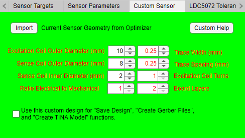 Figure 6-7 LDC5072 Sensor designer
Custom Sensor Tab
Figure 6-7 LDC5072 Sensor designer
Custom Sensor TabThe tool can create three SPICE model files by clicking the Create Spice Model button after completion of a design. The tool can also create Gerber files by clicking the Create Gerber Files button after the completion of the design.
The SPICE models are in the form of text files with .cir extensions. One file is for the sensor and target model (as shown in the Figure 6-4 above). One file is for the LDC5072 model, and one is a test bench that can run a transient simulation of the sensor+target+LDC5072. Details on how to best run the test bench simulation are provided in the section Running Simulations in Pspice
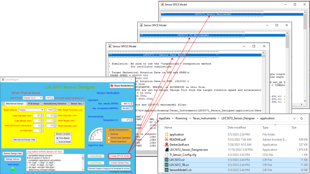 Figure 6-8 Spice Model Creation for the
Sensor, LDC5072 and a Test Bench
Figure 6-8 Spice Model Creation for the
Sensor, LDC5072 and a Test BenchClicking the Create Gerber Files button on the front panel makes the tool create a set of Gerber files for the target, sense coils and an evaluation PC board with the sense coils and an LDC5072-Q1 device. This also creates *.pdf files of those assemblies, as well as schematics, and part placement diagrams and displays these as a pop-up. All files are saved to the application folder when created (e.g. C:\Users\UserID\AppData\Roaming\Texas_Instruments\LDC5072_Sensor_Designer\application\SensorGerber#)
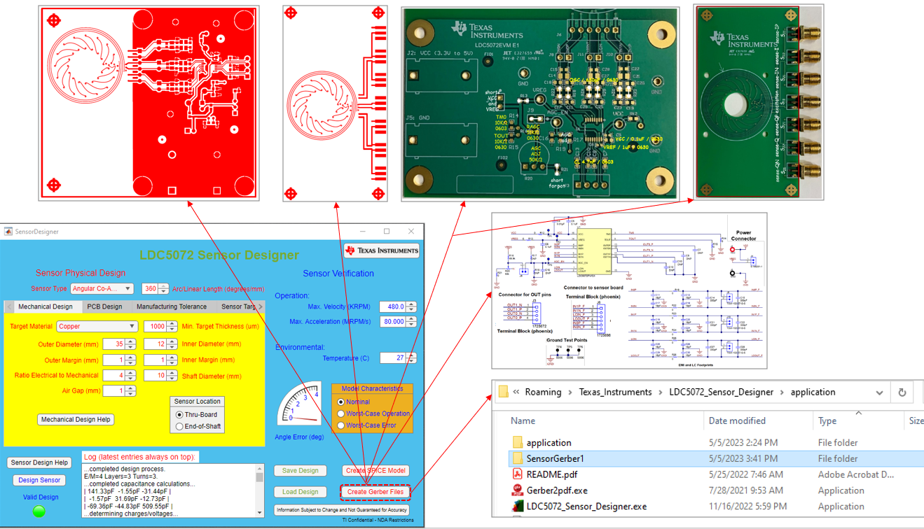 Figure 6-9 Gerber File Creation for the
Sensor, LDC5072 and a Test Bench