SNVA559C September 2012 – February 2019 LM2574 , LM2575-N , LM2575HV , LM2576 , LM2576HV , LM2577
-
Switching regulator fundamentals
- Trademarks
- 1 Switching Fundamentals
- 2 Switching Converter Topologies
- 3 Application Hints for Switching Regulators
- 4 Application Circuits
- 5 References and Related Products
- Revision History
2.1 Buck Regulator
The most commonly used switching converter is the Buck, which is used to down-convert a DC voltage to a lower DC voltage of the same polarity. This is essential in systems that use distributed power rails (like 24 V to 48 V), which must be locally converted to 15 V, 12 V or 5 V with very little power loss.
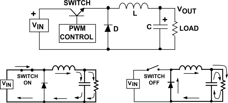
The buck converter uses a transistor as a switch that alternately connects and disconnects the input voltage to an inductor (see Figure 5).
 Figure 5. Buck Regulator
 The lower diagrams show the current flow paths (shown as the heavy lines) when the switch is on and off.
When the switch turns on, the input voltage is connected to the inductor. The difference between the input and output voltages is then forced across the inductor, causing current through the inductor to increase.
During the ON time, the inductor current flows into both the load and the output capacitor (the capacitor charges during this time).
When the switch is turned off, the input voltage applied to the inductor is removed. However, because the current in an inductor can not change instantly, the voltage across the inductor will adjust to hold the current constant.
The input end of the inductor is forced negative in voltage by the decreasing current, eventually reaching the point where the diode is turned on. The inductor current then flows through the load and back through the diode.
The capacitor discharges into the load during the OFF time, contributing to the total current being supplied to the load (the total load current during the switch OFF time is the sum of the inductor and capacitor current).
The shape of the current flowing in the inductor is similar to Figure 6.
 Figure 6. Buck Regulator Inductor Current
 As explained, the current through the inductor ramps up when the switch is on, and ramps down when the switch is off. The DC load current from the regulated output is the average value of the inductor current.
The peak-to-peak difference in the inductor current waveform is referred to as the inductor ripple current, and the inductor is typically selected large enough to keep this ripple current less than 20% to 30% of the rated DC current.