SNVA869 November 2020 LP875761-Q1
2 Power Solution
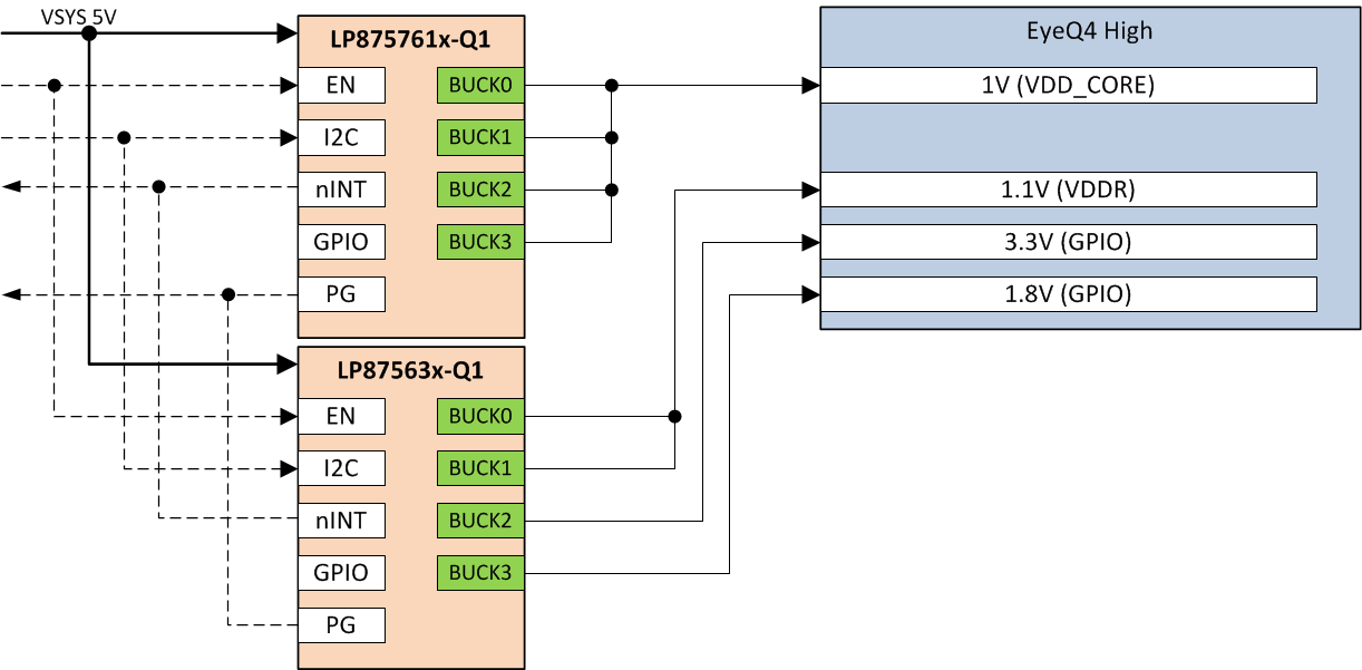
Figure 2-1 shows an example block diagram of LP875761-Q1 device powering the EyeQ4 High core rail, and LP87563x PMIC powering the other required rails. PMIC from the LP87563x family could be configured to power the other rails depending on use case.
 Figure 2-1 EyeQ4 High Power Solution
Block Diagram
Figure 2-1 EyeQ4 High Power Solution
Block DiagramAfter the devices are powered, the microcontroller can set the EN pin high to enable the PMIC. Startup delay of the LP875761ARNFRQ1 has been set to 0 ms. Full OTP register settings of LP875761ARNFRQ1 can be found in LP875761A-Q1 Technical Reference Manual. I2C can be used to read status registers and reset interrupts.