SNVAA19 May 2021 LP8863-Q1 , LP8864-Q1 , LP8864S-Q1 , LP8866-Q1 , LP8866S-Q1
5 Calculation of Feedback Resistor Values
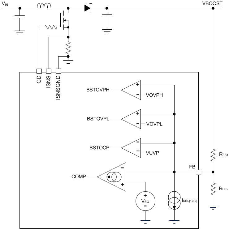
The resistive divider (RFB1, RFB2, RFB3) defines both the minimum and maximum adaptive boost voltage levels, as well as UVP and OVP levels. For feedback network using two-resistor method as shown in Figure 5-1, VMINBOOST, VMAXBOOST, VBOOST_UVP,MAX, VBOOST_OVP_LOW and VSTRING can be expressed in Equation 5, Equation 6, Equation 7, Equation 8, and Equation 9:


where:
- VBG is the band-gap voltage = 1.21 V
- RFB1 is the upper feedback resistor
- RFB2 is the lower feedback resistor
- ISEL_MAX is the maximum internal 11-bit DAC current ISEL = 38.7 μA
- VUVP is the undervoltage threshold at feedback pin = 0.886 V
- VOVPL is the overvoltage low level at feedback pin = 1.423 V
- 0.886 is the ratio of initial ISEL DAC current with respect to ISEL_MAX to set initial boot voltage during start-up
- VLED is the voltage cross an LED
- n is the number of LEDs in a string

Figure 5-1 Two-Resistor Feedback Network
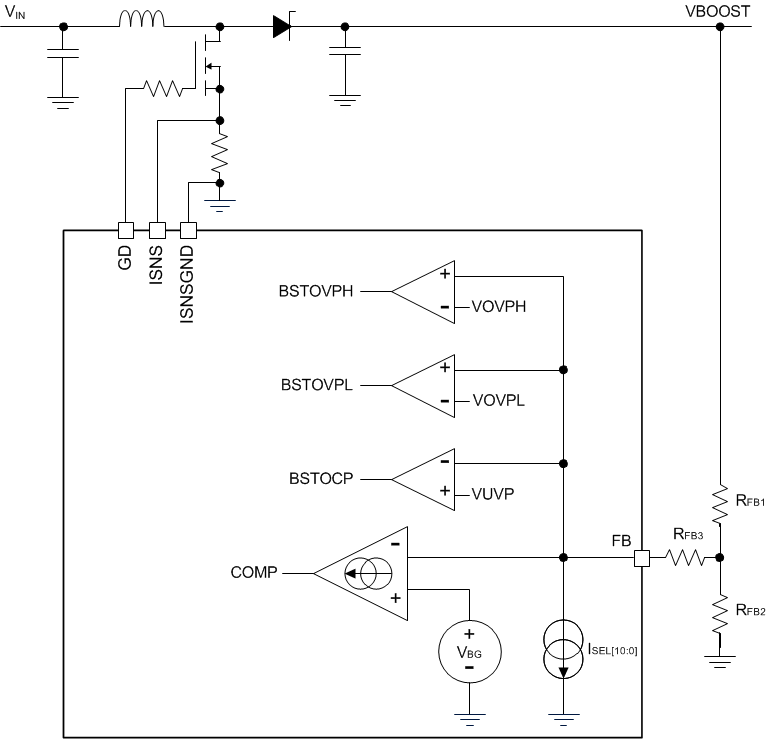
For feedback network using three-resistor method as shown in Figure 5-2, VMINBOOST, VMAXBOOST, VBOOST_UVP,MAX and VBOOST_OVP_LOW can be expressed in Equation 10, Equation 11, Equation 12, and Equation 13:


where:
- RFB3 is the third feedback resistor can be used in applications where less than 200-kΩ resistors are required.

Figure 5-2 Three-Resistor Feedback Network