SNVAA20 July 2021 DRV8833 , DRV8833 , LMR33630 , LMR33630
3.1.2 Power Converter Selection
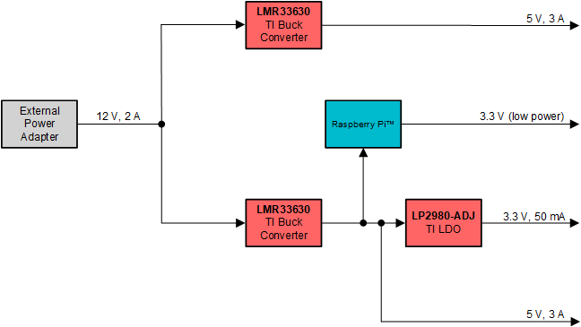
After determining the power requirements of this apparatus, and the required voltage and current levels for this design, suitable power converters must be selected. A standard 12-V power adapter is the starting point and this voltage is split into two 5-V rails. The first rail powers the motor via the motor driver and the second rail powers the Raspberry Pi and the rest of the components. To split the main power rail into two rails, two LMR33630 devices are utilized. These buck converters offer an easy-to-use pinout with a convenient leaded package in a small solution size. The second rail also feeds into an LDO, the LP2980-ADJ, which provides a quiet rail for the ADCs. Selecting a 5-V buck converter to power the LDO ensures that there is some headroom for the LDO, which has a 3.3-V output. The Raspberry Pi also provides a 3.3-V rail that can be used for the LED backlight, bringing the total number of voltage rails on the controller board to two 5-V rails, a 3.3-V rail, and a quiet, low-power 3.3-V rail as shown in Figure 3-1. It should be noted that an external Schottky diode is placed between the output (anode) and input (cathode) LDO to limit the reverse voltage across the LDO, in the event of the input voltage falling below the output voltage, which could cause an internal diode to latch on. This external leakage current of the Schottky diode must be minimal to ensure that the control loop can maintain control over the LDO output voltage.
 Figure 3-1 Controller Module Power
Rails