SNVSB35B May 2018 – June 2020
PRODUCTION DATA.
- 1 Features
- 2 Applications
- 3 Description
- 4 Revision History
- 5 Pin Configuration and Functions
- 6 Specifications
- 7 Detailed Description
- 8 Application and Implementation
- 9 Power Supply Recommendations
- 10Layout
- 11Device and Documentation Support
- 12Mechanical, Packaging, and Orderable Information
8.1.1 Programming Output Voltage
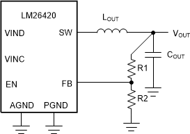
The output voltage is set using Equation 1 where R2 is connected between the FB pin and GND, and R1 is connected between VOUT and the FB pin. A good value for R2 is 10 kΩ. When designing a unity gain converter (VOUT = 0.8 V), R1 must be between 0 Ω and 100 Ω, and R2 must be on the order of 5 kΩ to 50 kΩ. 10 kΩ is the suggested value where R1 is the top feedback resistor and R2 is the bottom feedback resistor.
Equation 1. 

Equation 2. VREF = 0.80 V
 Figure 28. Programming VOUT
 To determine the maximum allowed resistor tolerance, use Equation 3:
Equation 3. 

where
- TOL is the set point accuracy of the regulator, is the tolerance of VFB.
Example:
VOUT = 2.5 V, with a setpoint accuracy of ±3.5%
Equation 4. 

Choose 1% resistors. If R2 = 10 kΩ, then R1 is 21.25 kΩ.