SNVU543A November 2016 – December 2016 LM5170 , LM5170-Q1
-
LM5170-Q1 EVM User Guide
- Trademarks
- 1 Features and Electrical Performance
- 2 Setup
- 3 Test Procedure
- 4
Test Data
- 4.1 Efficiency
- 4.2 Current Regulation and Monitoring
- 4.3 Typical Master Enable Power Up and Shutdown
- 4.4 Channel Enable and Disable
- 4.5 Dual-Channel Interleaving Operation
- 4.6 ISETA Tracking
- 4.7 Diode Emulation Preventing Negative Currents
- 4.8 Dynamic DIR Change
- 4.9 Step Load Response
- 4.10 OVP
- 4.11 Output Short Circuit
- 5 Design Files
- Revision History
2.2 Bench Setup
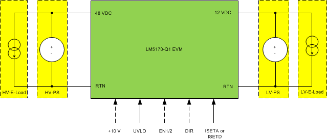
Figure 3 shows the typical bench setup to operate the EVM in the bidirectional power system environment. The combination of the Electronic Load (E-Load) and bench Power Supply (PS) emulates a battery capable of both sourcing and sinking current. A relatively Higher Voltage Power Supply (HV-PS) and E-Load (HV-E-Load) should be used for the 48VDC-port, and a Lower Voltage Power Supply (LV-PS) and E-Load (LV-E-Load) for the 12VDC-port. The external control signals shown as dashed lines can also be created with the onboard headers.
 Figure 3. Bidirectional Converter Bench Setup
 To operate the EVM to full power, the initial setup should follow the guidelines below:
- Set the LV-E-Load to Constant Current (CC) of 62 A
- Set the LV-PS voltage at 12 V, and the current limit at 63 A
- Set the HV-E-Load to CC of 14 A
- Set the HV-PS voltage at 48 V, and the current limit at 15 A
Note that in Buck Mode operation, the HV-E-load can be turned off, and in Boost Mode operation, the LV-E-load can be turned off. If the output voltage loop is closed, the LV-PS can be disconnected in Buck Mode operation. In Boost Mode operation, the HV-PS is required for Boost start-up, which is limited by the onboard circuit breaker function. If the circuit breaker MOSFETS are shorted and J3 is closed, the HV-PS is not needed for Boost Mode operation.