SNVU731 November   2020 LP8864-Q1


  1.   Trademarks
  2. 1Introduction
    1. 1.1 Features
    2. 1.2 Applications
  3. 2Test Setup
    1. 2.1 LP8864EVM Kit
    2. 2.2 System and Equipment Requirements
    3. 2.3 Hardware Setup
    4. 2.4 Software Installation
    5. 2.5 Quick Start-Up Procedure
    6. 2.6 Additional GUI Functions
      1. 2.6.1 Monitor Faults Page
      2. 2.6.2 Diagnostics Page
      3. 2.6.3 Register Map Page
    7. 2.7 Instructions for Standalone Evaluation
  4. 3LP8864EVM Board Layout
  5. 4LP8864EVM Schematic
  6. 5 LP8864EVM Bill of Materials
  7. 6LED Load Board

Hardware Setup

Figure 2-2 shows the hardware setup of the LP8864EVM.

  • Connect a 12-V external power supply between the power input terminals VBAT+ and GNDin on the LP8864EVM
  • Connect the USB2ANY module to the PC with the USB cable
  • Connect the USB2ANY module to the LP8864EVM with the provided ribbon cable
  • Connect the LP8864EVM to the LP886X-LEDLOAD-EVM with a 5-position ribbon cable
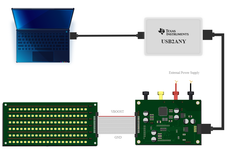
GUID-DC937E42-53E5-4E01-816E-BBBBF9F3E306-low.pngFigure 2-2 LP8864EVM Hardware Setup