SPMA072 March   2015 TM4C1294KCPDT , TM4C1294KCPDT , TM4C1294NCPDT , TM4C1294NCPDT , TM4C1294NCZAD , TM4C1294NCZAD , TM4C1299KCZAD , TM4C1299KCZAD , TM4C1299NCZAD , TM4C1299NCZAD , TM4C129EKCPDT , TM4C129EKCPDT , TM4C129ENCPDT , TM4C129ENCPDT , TM4C129ENCZAD , TM4C129ENCZAD , TM4C129XKCZAD , TM4C129XKCZAD , TM4C129XNCZAD , TM4C129XNCZAD


  1.   Serial to Ethernet Converter for TM4C129x Microcontrollers Using RTOS
    1.     Trademarks
    2. 1 Introduction
    3. 2 Software Description
    4. 3 Set Up and Program enet_s2e Application
      1. 3.1 Set Up enet_s2e Application
      2. 3.2 Software Modification for DK-TM4C129X
      3. 3.3 Program the enet_s2e Application
    5. 4 Demonstration
      1. 4.1 Set Up EK-TM4C1294XL Board and PC
      2. 4.2 Demonstration
    6. 5 Configuration Webserver
      1. 5.1 Access the Configuration Webserver
        1. 5.1.1 Using the Debug Port
        2. 5.1.2 Using the Finder Utility
      2. 5.2 Different Pages Hosted on the Configuration Webserver
        1. 5.2.1 S2E Status Page
        2. 5.2.2 S2E Port 0 and Port 1 Settings Page
        3. 5.2.3 S2E Miscellaneous Settings Page
    7. 6 Flow Control
    8. 7 Additional Hardware
      1. 7.1 Schematic of RS-232 Level Shifter
      2. 7.2 Connections
      3. 7.3 Bill of Materials (BOM)
    9. 8 References

Demonstration

A simple set up, like the one shown in Figure 2, demonstrates the serial-to-Ethernet functionality of TM4C129x. Section 4.1 and Section 4.2 provide instructions on how to use two Terminal windows on a PC to loop data back and forth between a serial peripheral and Ethernet peripheral of the PC using the S2E module. Although either of the Serial-to-Telnet port pairs could be used for this demonstration, Port 0 is used in this documentation.
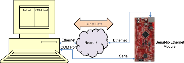
Figure02_SPMA072.gifFigure 2. S2E Demonstration Representation