SPMA082 August 2021 TM4C1230C3PM , TM4C1230D5PM , TM4C1230E6PM , TM4C1230H6PM , TM4C1231C3PM , TM4C1231D5PM , TM4C1231D5PZ , TM4C1231E6PM , TM4C1231E6PZ , TM4C1231H6PGE , TM4C1231H6PM , TM4C1231H6PZ , TM4C1232C3PM , TM4C1232D5PM , TM4C1232E6PM , TM4C1232H6PM , TM4C1233C3PM , TM4C1233D5PM , TM4C1233D5PZ , TM4C1233E6PM , TM4C1233E6PZ , TM4C1233H6PGE , TM4C1233H6PM , TM4C1233H6PZ , TM4C1236D5PM , TM4C1236E6PM , TM4C1236H6PM , TM4C1237D5PM , TM4C1237D5PZ , TM4C1237E6PM , TM4C1237E6PZ , TM4C1237H6PGE , TM4C1237H6PM , TM4C1237H6PZ , TM4C123AE6PM , TM4C123AH6PM , TM4C123BE6PM , TM4C123BE6PZ , TM4C123BH6PGE , TM4C123BH6PM , TM4C123BH6PZ , TM4C123BH6ZRB , TM4C123FE6PM , TM4C123FH6PM , TM4C123GE6PM , TM4C123GE6PZ , TM4C123GH6PGE , TM4C123GH6PM , TM4C123GH6PZ , TM4C123GH6ZRB , TM4C1290NCPDT , TM4C1290NCZAD , TM4C1292NCPDT , TM4C1292NCZAD , TM4C1294KCPDT , TM4C1294NCPDT , TM4C1294NCZAD , TM4C1297NCZAD , TM4C1299KCZAD , TM4C1299NCZAD , TM4C129CNCPDT , TM4C129CNCZAD , TM4C129DNCPDT , TM4C129DNCZAD , TM4C129EKCPDT , TM4C129ENCPDT , TM4C129ENCZAD , TM4C129LNCZAD , TM4C129XKCZAD , TM4C129XNCZAD
1.1 Typical Interfaces
Depending on the particular TFT panel size and resolution, some driver ICs may support multiple interfaces to communicate with the host controller. The interfaces are normally selectable on the module FPC or through firmware initialization.
- SPI interface. This is the most simple and low pin-count interface which is normally reserved for character-based LCD or small TFT panels that require slow frame rate operation. Any MCU with a SPI interface can interact with the displays supporting this interface. The BOOSTXL-K350QVG-S1 BoosterPack is one such example that can interface with TI’s various LaunchPad's through the SPI interface.
 Figure 1-3 SPI Interface to the Display Module
 - MPU interface. This is a parallel bus interface. This is normally the interface of choice when the display module contains an integrated display controller. For example, the Kentec320x240x16 QVGA Display has the built-in SSD2119 display controller IC. The MCU uses the parallel bus interface to write the frame buffer on the SSD2119 controller. There are two types of MPU interfaces – Motorola 6800 and Intel 8080. 8080 is a more popular interface than 6800. This interface consists 4/8/9/16 bits data, Chip-Select (CS) , Data/Instruction Select (RS), Read-Write (RD) and Write-Enable (WR). Figure 2-3 shows the signal mapping on TM4C129 MCU.
 Figure 1-4 MPU Interface to the Display Module
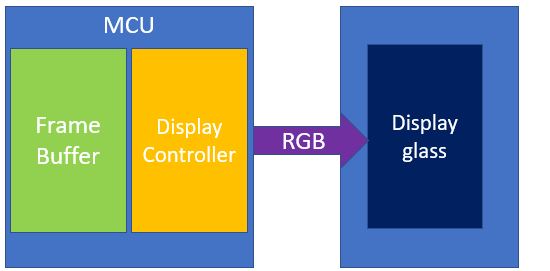
 - RGB interface. This is a parallel bus interface that works for displays without a frame buffer. The MCU is responsible for updating the display by providing the timing signals (HSYNC, VSYNC, OE, CLK) and the RGB sub-pix data (16 bits, 18 bits, 24 bits).
- In active TFT mode, the HSYNC (LCDLP signal) acts as a horizontal line clock. HSYNC toggles after all pixels in a horizontal line have been transmitted to the LCD and a programmable number of pixel clock wait states have elapsed both at the beginning and end of each line.
- In active TFT mode, the VSYNC (LCDFP signal) is the vertical frame clock. VSYNC toggles after all lines in a frame have been transmitted to the LCD and a programmable number of line clock cycles has elapsed at the beginning and end of each frame.
- In active TFT mode, the OE (LCDAC signal) acts as an output enable signal. It is used to signal the external LCD that the data is valid on the data bus.
 Figure 1-5 RGB Interface to the Display Glass