SPMA084 December 2021 TM4C1230C3PM , TM4C1230C3PM , TM4C1230D5PM , TM4C1230D5PM , TM4C1230E6PM , TM4C1230E6PM , TM4C1230H6PM , TM4C1230H6PM , TM4C1231C3PM , TM4C1231C3PM , TM4C1231D5PM , TM4C1231D5PM , TM4C1231D5PZ , TM4C1231D5PZ , TM4C1231E6PM , TM4C1231E6PM , TM4C1231E6PZ , TM4C1231E6PZ , TM4C1231H6PGE , TM4C1231H6PGE , TM4C1231H6PM , TM4C1231H6PM , TM4C1231H6PZ , TM4C1231H6PZ , TM4C1232C3PM , TM4C1232C3PM , TM4C1232D5PM , TM4C1232D5PM , TM4C1232E6PM , TM4C1232E6PM , TM4C1232H6PM , TM4C1232H6PM , TM4C1233C3PM , TM4C1233C3PM , TM4C1233D5PM , TM4C1233D5PM , TM4C1233D5PZ , TM4C1233D5PZ , TM4C1233E6PM , TM4C1233E6PM , TM4C1233E6PZ , TM4C1233E6PZ , TM4C1233H6PGE , TM4C1233H6PGE , TM4C1233H6PM , TM4C1233H6PM , TM4C1233H6PZ , TM4C1233H6PZ , TM4C1236D5PM , TM4C1236D5PM , TM4C1236E6PM , TM4C1236E6PM , TM4C1236H6PM , TM4C1236H6PM , TM4C1237D5PM , TM4C1237D5PM , TM4C1237D5PZ , TM4C1237D5PZ , TM4C1237E6PM , TM4C1237E6PM , TM4C1237E6PZ , TM4C1237E6PZ , TM4C1237H6PGE , TM4C1237H6PGE , TM4C1237H6PM , TM4C1237H6PM , TM4C1237H6PZ , TM4C1237H6PZ , TM4C123AE6PM , TM4C123AE6PM , TM4C123AH6PM , TM4C123AH6PM , TM4C123BE6PM , TM4C123BE6PM , TM4C123BE6PZ , TM4C123BE6PZ , TM4C123BH6PGE , TM4C123BH6PGE , TM4C123BH6PM , TM4C123BH6PM , TM4C123BH6PZ , TM4C123BH6PZ , TM4C123BH6ZRB , TM4C123BH6ZRB , TM4C123FE6PM , TM4C123FE6PM , TM4C123FH6PM , TM4C123FH6PM , TM4C123GE6PM , TM4C123GE6PM , TM4C123GE6PZ , TM4C123GE6PZ , TM4C123GH6PGE , TM4C123GH6PGE , TM4C123GH6PM , TM4C123GH6PM , TM4C123GH6PZ , TM4C123GH6PZ , TM4C123GH6ZRB , TM4C123GH6ZRB , TM4C1290NCPDT , TM4C1290NCPDT , TM4C1290NCZAD , TM4C1290NCZAD , TM4C1292NCPDT , TM4C1292NCPDT , TM4C1292NCZAD , TM4C1292NCZAD , TM4C1294KCPDT , TM4C1294KCPDT , TM4C1294NCPDT , TM4C1294NCPDT , TM4C1294NCZAD , TM4C1294NCZAD , TM4C1297NCZAD , TM4C1297NCZAD , TM4C1299KCZAD , TM4C1299KCZAD , TM4C1299NCZAD , TM4C1299NCZAD , TM4C129CNCPDT , TM4C129CNCPDT , TM4C129CNCZAD , TM4C129CNCZAD , TM4C129DNCPDT , TM4C129DNCPDT , TM4C129DNCZAD , TM4C129DNCZAD , TM4C129EKCPDT , TM4C129EKCPDT , TM4C129ENCPDT , TM4C129ENCPDT , TM4C129ENCZAD , TM4C129ENCZAD , TM4C129LNCZAD , TM4C129LNCZAD , TM4C129XKCZAD , TM4C129XKCZAD , TM4C129XNCZAD , TM4C129XNCZAD
- Trademarks
- 1Introduction
- 2Pulse Width Modulation (PWM) emulation of a DAC
- 3Audio Sampling Rate and Resolution Analysis
- 4Audio File Data Format
- 5Hardware Setup
-
6Application Examples
- 6.1 Examples: audio_playback_internal_wavefile_by_PWM_EKTM4C129 and audio_playback_internal_wavefile_by_SPIDAC_EKTM4C129
- 6.2 Examples: audio_playback_internal_wavefile_by_PWM_EKTM4C123 and audio_playback_internal_wavefile_by_SPIDAC_EKTM4C123
- 6.3 Examples: audio_playback_internal_wavefile_by_PWM and audio_playback_internal_wavefile_by_SPIDAC
- 6.4 Examples: audio_playback_with_sdcard_by_PWM and audio_playback_with_sdcard_by_SPIDAC
- 7Download and Import the Examples
- 8References
2 Pulse Width Modulation (PWM) emulation of a DAC
Not all microcontrollers have an integrate DAC on chip, but almost all have the capability to generate PWM signals either with a dedicated peripheral or with a timer module. PWM is a low-cost way to control analog devices (a speaker) with a digital output. PWM emulates an analog signal by means of controlling the duty cycle. Suppose a 100% duty cycle PWM is produced from a 3.3 V MCU, it is easily expected the PWM will produce a 3.3 V DC level signal. A 0% duty cycle PWM is expected to produce a 0 V DC signal as well. What about a 10% duty cycle periodic PWM? If a multimeter is used to measure the PWM output, it is not surprised the multimeter measures 3.3 V * 10% = 0.33 V. A 50% duty cycle PWM will measure 3.3 V * 50% = 1.65 V. This relationship between duty cycle and measured voltage is fairly intuitive. This can be concluded with a simple equation as shown in Equation 1:
Earlier in the Section 1, it was mentioned that each time an analog audio signal is sampled, the signal is recorded as a binary number and the length of the binary numbers is called the resolution. In another word, the resolution expresses the number of discrete steps an analog signal can be represented. If the length of binary numbers is 16, this is denoted as 16-bit resolution. A 16-bit binary value can produce 216 = 65536 discrete steps of a signal. Dividing 3.3 V by 65536 is equal to about 50 µV for each step.
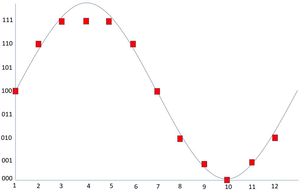
Figure 2-1 shows an example analog signal that is digitized with 12 evenly spaced samples at 3-bit resolution. With only 3 bits of resolution, there are only 8 discrete steps. At this resolution, severe quantization error can result which is the difference between the analog signal and the closest available digital value at each sampling instant from the ADC. In Figure 2-1, samples 3, 4 and 5 are converted to the same digital value when they are different in its analog form at the respective sample points.
 Figure 2-1 Example Analog Signal
Digitized With 12 Samples at 3-Bit Resolution
Figure 2-1 Example Analog Signal
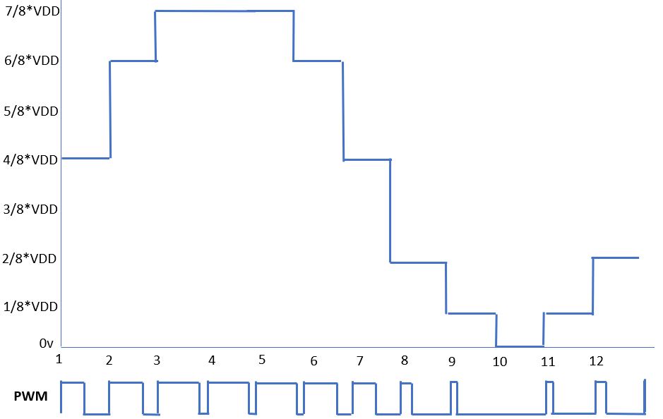
Digitized With 12 Samples at 3-Bit ResolutionTo recreate the analog signal in Figure 2-1 using PWM, the duty cycle is obtained by dividing the digital value at each sample point by the bit depth which is 23 = 8.
Figure 2-2 illustrates the reproduction of the analog signal based on the sampling rate and resolution shown in Figure 2-1. Although it resembles the original analog signal but it does not come close to true reproduction. Improvements can be made by increasing the sampling rate and resolution. Imagine the original analog signal was digitized at 8 kHz (8000 samples per second) and 8 bit (256 discrete steps) resolution or higher, the original analog signal will be reproduced by the PWM DAC method at much higher accuracy.
 Figure 2-2 Reproduction of Analog Signal
Using PWM DAC