SPRABN2A March 2019 – December 2019 AM3352 , AM3354 , AM3356 , AM3357 , AM3358 , AM3358-EP , AM3359
-
AM335x Schematic Checklist
- Trademarks
- 1 Introduction
- 2
Recommendations Specific to AM335x
- 2.1 Unused Signals
- 2.2 SYSBOOT Configuration and Required Termination
- 2.3 System Issues
- 2.4 Low-Power Considerations
- 2.5 Clocking
- 2.6 General DDR Guidelines
- 2.7 MultiMedia Card/ (MMC)
- 2.8 Inter-Integrated Circuit (I2C)
- 2.9 LCD
- 2.10 Power
- 2.11 Touchscreen
- 2.12 USB
- 2.13 External Interrupt (EXTINTn)
- 2.14 Ethernet
- 3 References
- Revision History
2.9 LCD
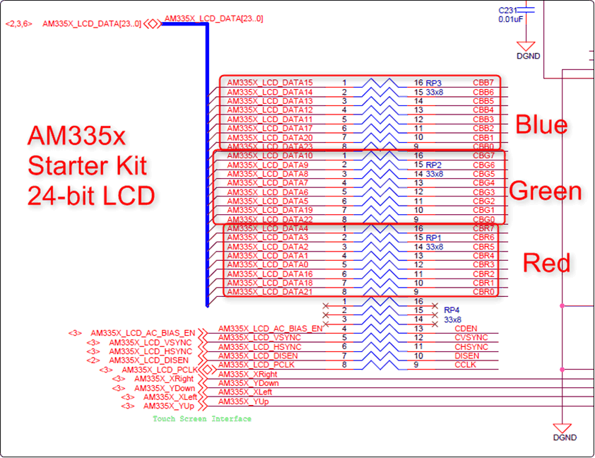
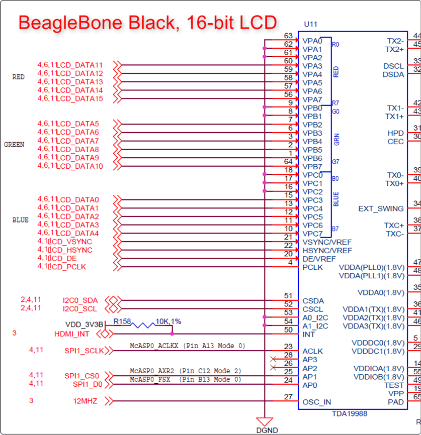
Be sure to consult the silicon errata for the proper pinout of the LCD interface. There is a usage note titled, "LCD: Color Assignments of LCD_DATA Terminals" in the device Silicon Errata.
Note that the AM335x EVM "fixes" the pin mapping through a CPLD on the daughterboard, so be extra careful to get the proper mapping!
- A good example of a 24-bit hookup comes from the AM335x Starter Kit shown in Figure 1.
- A good example of a 16-bit hookup comes from the BeagleBone Black that is shown in Figure 2. In this case, the other LCD pins were preserved for use by capes.
- Notice that Red and Blue swap positions depending on whether you are outputting in 16-bit mode vs 24-bit mode (that is, the errata).
 Figure 1. AM335x Starter Kit, 24-Bit LCD
  Figure 2. BeagleBone Black, 16-Bit LCD