SPRACK9 February 2019 AM1705 , AM1707 , AM1806 , AM1808 , OMAP-L132 , OMAP-L137 , OMAP-L138 , TMS320C6742 , TMS320C6745 , TMS320C6746 , TMS320C6747 , TMS320C6748
-
OMAP-L13x/C674x/AM1x schematic review guidelines
- Trademarks
- 1 Introduction
- 2 Recommendations Specific to OMAP-L1x/TMS320C674x/AM1x
- 3 BGA PCB Design
- 4 Power Management Solutions
- 5 References
- A XDS Connector Design Checklist
- B Connecting NOR Flash to OMAP-L138
2.4.8.4.1 Cautionary note - USB PHY off while host is still powered on
When the USB PHY is powered off while still connected to a host that is powered on, the customer may notice leakage on the 3.3 V supply. This is because there is a path between VBUS and the 3.3 V supply rail that allows current to leak from the powered VBUS to the 3.3 V supply rail.
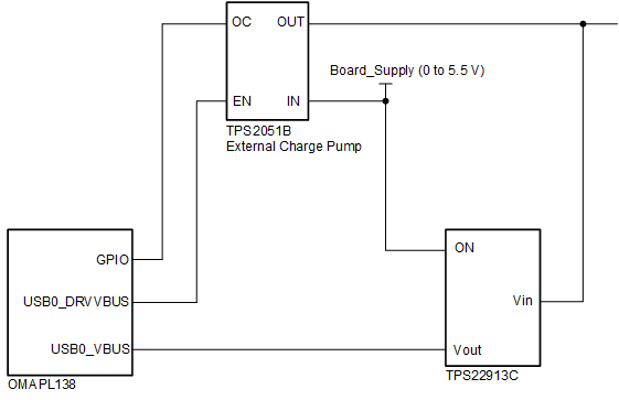
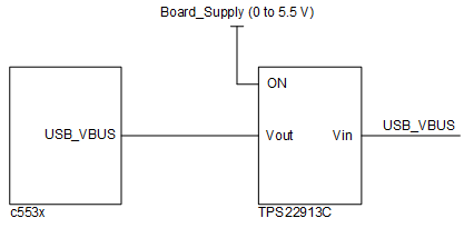
If the USB PHY remains powered off for an indefinite period of time while connected to a powered VBUS, there is a risk of long-term stress on the PHY’s internal circuitry. TI therefore recommends that customers isolate the input USB0_VBUS from the VBUS until the device is powered up. This can be accomplished by implementing a discrete load switch such as TPS22913. Some example circuits are shown in Figure 2 and Figure 3.
If the SoC supports OTG Host/Device mode:
 Figure 2. Isolation Circuit for OTG Host/Device Mode
 If the SoC supports Device-only mode:
 Figure 3. Isolation Circuit for Device-Only Mode