SPRACN3 September 2019 66AK2E05 , 66AK2H06 , 66AK2H12 , 66AK2H14 , 66AK2L06 , AM5K2E02 , AM5K2E04
-
Using ARM ROM Bootloader on Keystone II Devices
- Trademarks
- 1 Keystone2 Boot loader Overview
- 2 Boot Examples Package Download
- 3 Software Dependencies
- 4 Supported Hardware
- 5 Software Features
- 6 Directory Structure
- 7 Building the Examples
- 8 Description of the Examples
- 9 Boot Utilities
- 10 Frequently Asked Questions (FAQ)
- 11 References
8.4.6 Running Ethernet Examples
Ethernet boot is a slave boot mode that requires the host to pass the blob boot image to the target running a DHCP server. Connect the ethernet cable to the host and your switch, and connect another cable from you switch to the EVM. Make sure you do not run this in a high network traffic environment. In order to run the DHCP server on the host Windows machine, use an open source TFTP32 utility in admin mode and configure our host to a static IP expected by the target.
- Location of Boot image binaries:
- examples/<k2 device>/eth/singleStage/bin/ethImage.dat
- examples/<k2 device>/eth/multiStage/bin/uartStage1.dat
- examples/<k2 device>/eth/multiStage/bin/ethernetStage2.dat
- TFTP host utility download:
- Setting up the host for ethernet boot:
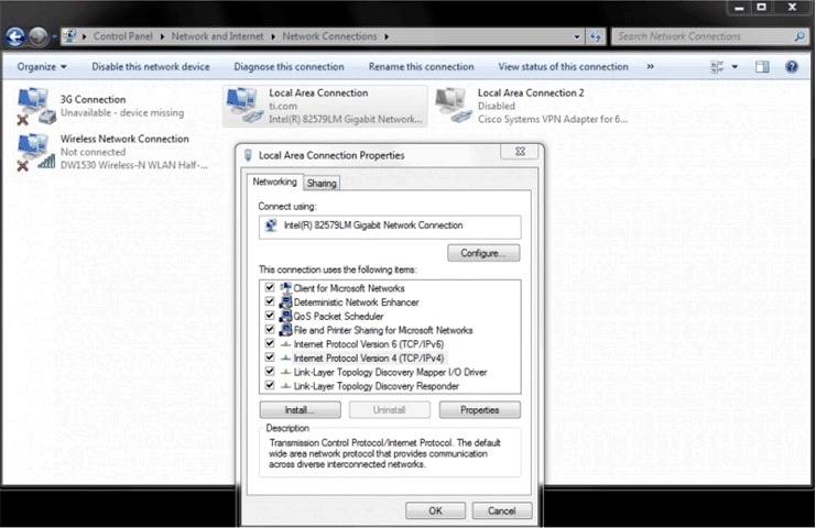
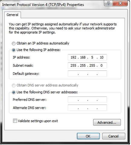
- Setup Static IP on the host machine by setting the IPv4 setting of the Wired LAN settings. Set the Static IP to 192.168.5.10 as shown in Figure 5.
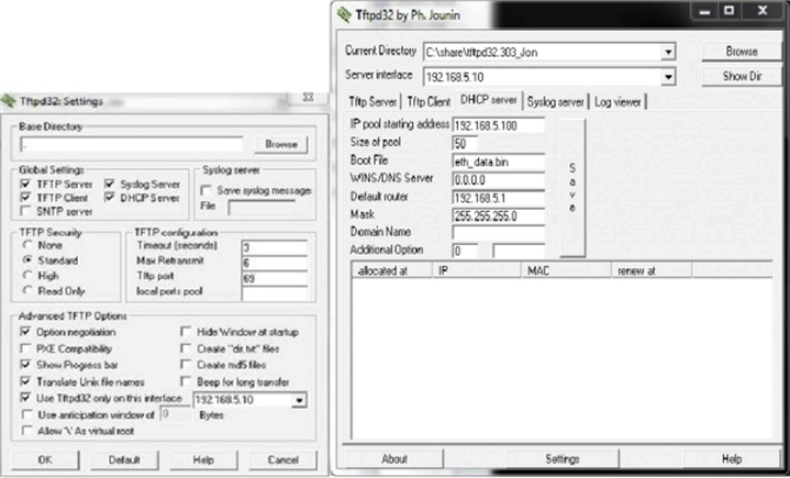
- Configure the DHCP Server settings in the TFTP32 utility as shown in Figure 6.

 Figure 5. Static IP Configuration on Host PC
  Figure 6. TFTP Transfer Configuration for Ethernet Boot
Fixing the issue with BMC firmware and boot switches to boot Arm over ethernet on K2H EVM.
Some earlier revisions of the EVM have an issue with the settings required for setting up the EVM for ethernet boot.
In order to fix the issue, follow the steps below:
- Connect your host to the serial port and connect to both the BMC console port and the Serial port. Using the settings described in the serial port setup section of the wiki.
- Setup the boot switches to Ethernet boot(p[1:4]=0101) using the settings described in Section 8.4.1.
- Power on the EVM. You should see the Arm ENET boot mode on the LCD screen in the logs displayed along with BOOT COMPLETE.
- On the BMC port, type the following:
>bootmode #8 0 115EEB
>bootmode #8
>reboot
Or
> setboot 115EEB
>fullrst
- Running and verifying the Ethernet single stage boot on the K2H devices:
- Copy the Ethernet single stage boot image to the TFTP32 folder and rename the file to eth_data.bin.
- Power on the EVM, set the ethernet boot in BMC firmware; when the device reboots, make sure the tftpd32 utitlity is running and configured as described in the previous section. When EVM boots in ethernet boot mode, it will send a bootp. If you do not see uboot come up on the Serial port, check if you are able to see bootp packet by using Wireshark utility.
- After the BOOTP is received, you will see the transfer of the ethernet boot image and the UART messages when the boot completes:
Core 0 standing by.... Core 1 standing by.... Core 2 standing by.... Core 3 standing by.... - Running and verifying the Ethernet mutli stage boot: on K2H/K2E devices:
- Load the first stage over UART:
- Set the boot switches of the EVM to UART boot.
- Connect the serial cable from the EVM to the host and launch hyperterminal or Tera term and configure the serial terminal connection to 115200 bps.
- Run the TFTP32 utility and power on the EVM.
- After the UART first stage boots, the device switches to ethernet boot and loads the second stage over Ethernet.
- Load the first stage over I2C:
- Set the boot switches of the EVM to No boot.
- Copy the second stage image to the TFTP32 utility folder and rename it to eth_data. Run the TFTP32 utility using admin privileges as described in the single stage boot section.
- Use the I2C EEPROM writer from MCSDK 3.x as described in the I2C boot example to flash the first stage to the EEPROM.
- After you have flashed the image, switch the boot switches to I2C boot. Before you power on the EVM, ensure the TFTP32 utility is running with the second stage copied over.
The Ethernet multi-stage example runs the first stage over UART or I2C and then re-enters the boot to load the second stage over ethernet.
The Ethernet multi-stage example runs the first stage over UART or I2C and then re-enters boot to load the second stage over ethernet.
NOTE
On K2E EVM, connect the ethernet cable to the top port of the ethernet switch. On K2H the device can boot first stage from either port 1 or port 2.
NOTE
On K2E EVM, connect the ethernet cable to the top port of the ethernet switch. On K2H the device can boot first stage from either port 1 or port 2.