SPRACO3 October 2019 INA240 , LMG5200 , TMS320F280021 , TMS320F280021-Q1 , TMS320F280023 , TMS320F280023-Q1 , TMS320F280023C , TMS320F280025 , TMS320F280025-Q1 , TMS320F280025C , TMS320F280025C-Q1 , TMS320F280040-Q1 , TMS320F280040C-Q1 , TMS320F280041 , TMS320F280041-Q1 , TMS320F280041C , TMS320F280041C-Q1 , TMS320F280045 , TMS320F280048-Q1 , TMS320F280048C-Q1 , TMS320F280049 , TMS320F280049-Q1 , TMS320F280049C , TMS320F280049C-Q1 , TMS320F28374D , TMS320F28374S , TMS320F28375D , TMS320F28375S , TMS320F28375S-Q1 , TMS320F28376D , TMS320F28376S , TMS320F28377D , TMS320F28377D-EP , TMS320F28377D-Q1 , TMS320F28377S , TMS320F28377S-Q1 , TMS320F28378D , TMS320F28378S , TMS320F28379D , TMS320F28379D-Q1 , TMS320F28379S
-
Dual-Axis Motor Control Using FCL and SFRA On a Single C2000 MCU
- Trademarks
- 1 Introduction
- 2 Benefits of the C2000 for High-Bandwidth Current Loop
- 3 Current Loops in Servo Drives
- 4 PWM Update Latency for Dual Motor
- 5 Outline of the Fast Current Loop Library
- 6 Evaluation Platform Setup
- 7 System Software Integration and Testing
- 8 Summary
- 9 References
7.4 Incremental Build Level 4
Assuming the previous section is completed successfully, this section verifies the speed PI module and speed loop. The implementation block diagram is given in Figure 28. The motor shafts must be kept disconnected to run these motors at different speed settings simultaneously or only one motor can be tested at a given time. When the motor is commanded to run, it is subjected to an initial alignment stage where the electrical angle and the QEP angle count are set to zero. After ensuring a stable alignment, the motor starts running.
 Figure 28. Level 4 Block Diagram Showing Speed Loop for Dual Motor With Inner FCL
 - Open "dual_axis_servo_drive_settings.h" and select level 4 incremental build option by setting the BUILDLEVEL to FCL_LEVEL4 (#define BUILDLEVEL FCL_LEVEL4). The current loop regulator can be selected to be the PI controller or the complex controller by setting FCL_CNTLR to PI_CNTLR or CMPLX_CNTLR.
- Right-click on the project name, and then click Rebuild Project.
- When the build is complete, click the Debug button, reset the CPU, restart, enable real-time mode, and run. In the software, within the 'motorVars[0]' structure, the key variables to add, adjust, or monitor are summarized as follows:
- motorVars[0].runMotor : flag to MOTOR_RUN or MOTOR_STOP
- motorVars[0].speedRef: for changing the rotor speed in per-unit.
- Set 'enableFlag' to 1 in the expressions window. The variables named 'motorVars[0].isrTicker' and 'motorVars[1].isrTicker' are incrementally increased as shown in Expressions window to confirm the interrupts are working properly.
- Set 'motorVars[0].speedRef' to 0.3 pu (or another suitable value if the base speed is different).
- Add 'motorVars[0].pid_spd' variable to the Expressions window.
- Gradually increase voltage at DC power supply to get an appropriate DC-bus voltage.
- Add the soft-switch variable 'motorVars[0].ptrFCL->lsw' to the watch window to start the motor. The variable is auto promoted in a sequence inside the FCL. In the code, 'motorVars[0].ptrFCL->lsw' manages the loop setting as follows:
- lsw = ENC_ALIGNMENT --> lock the rotor of the motor.
- lsw = ENC_WAIT_FOR_INDEX --> motor in running mode, waiting for first instance of QEP Index pulse.
- lsw = ENC_CALIBRATION_DONE --> motor in running mode, first Index pulse of encoder occurred.
- Set 'motorVars[0].runMotor' flag to MOTOR_RUN to run the motor, now the motor runs with this reference speed (0.3 pu). Compare the 'motorVars[0].speed.Speed' with 'motorVars[0].speedRef' in the watch windows with the continuous refresh feature to see whether or not it is nearly the same.
- To confirm this speed PID module, try different values of 'speedRef' (positive or negative). The P, I, and D gains may be tweaked to get a satisfactory response.
- At a very low speed range, the performance of the speed response relies heavily on the good rotor position angle provided by the QEP encoder.
- Set ‘motorVars[0].runMotor’ to MOTOR_STOP to stop the motor.
- Bring the system to a safe stop by reducing the bus voltage, taking the controller out of real-time mode, and resetting.
The same set of tests can be done on motor 2 by working with structure variable 'motorVars[1]'.
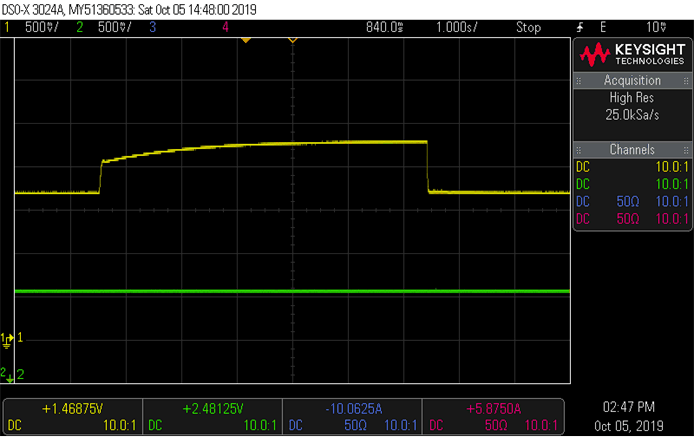
Figure 29 shows flux and torque currents in the synchronous reference frame under a step load and 0.6 pu speed. The waveform of channel 1 represents the feedback Q-axis current (torque current), channel 2 represents the feedback D-axis current (flux current).
 Figure 29. Flux and Torque Current Under Step-Load and 0.6-pu Speed