SPRACO3 October 2019 INA240 , LMG5200 , TMS320F280021 , TMS320F280021-Q1 , TMS320F280023 , TMS320F280023-Q1 , TMS320F280023C , TMS320F280025 , TMS320F280025-Q1 , TMS320F280025C , TMS320F280025C-Q1 , TMS320F280040-Q1 , TMS320F280040C-Q1 , TMS320F280041 , TMS320F280041-Q1 , TMS320F280041C , TMS320F280041C-Q1 , TMS320F280045 , TMS320F280048-Q1 , TMS320F280048C-Q1 , TMS320F280049 , TMS320F280049-Q1 , TMS320F280049C , TMS320F280049C-Q1 , TMS320F28374D , TMS320F28374S , TMS320F28375D , TMS320F28375S , TMS320F28375S-Q1 , TMS320F28376D , TMS320F28376S , TMS320F28377D , TMS320F28377D-EP , TMS320F28377D-Q1 , TMS320F28377S , TMS320F28377S-Q1 , TMS320F28378D , TMS320F28378S , TMS320F28379D , TMS320F28379D-Q1 , TMS320F28379S
-
Dual-Axis Motor Control Using FCL and SFRA On a Single C2000 MCU
- Trademarks
- 1 Introduction
- 2 Benefits of the C2000 for High-Bandwidth Current Loop
- 3 Current Loops in Servo Drives
- 4 PWM Update Latency for Dual Motor
- 5 Outline of the Fast Current Loop Library
- 6 Evaluation Platform Setup
- 7 System Software Integration and Testing
- 8 Summary
- 9 References
7.6.8 Phase Margin vs Gain Crossover Frequency
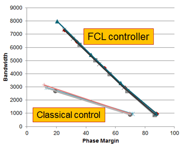
By varying the control bandwidth and repeating these tests and noting down the resulting gain cross over frequency and phase margin, a set of plots are obtained for Id loop as shown in Figure 40. Two sets of tests are performed: one based on classical current control method and the other based on FCL. Both these tests were performed using different current regulators. They all gave converging results.
 Figure 40. Plot of Gain Cross over Frequency vs Phase Margin as Experimentally Obtained