SPRACO3 October 2019 INA240 , LMG5200 , TMS320F280021 , TMS320F280021-Q1 , TMS320F280023 , TMS320F280023-Q1 , TMS320F280023C , TMS320F280025 , TMS320F280025-Q1 , TMS320F280025C , TMS320F280025C-Q1 , TMS320F280040-Q1 , TMS320F280040C-Q1 , TMS320F280041 , TMS320F280041-Q1 , TMS320F280041C , TMS320F280041C-Q1 , TMS320F280045 , TMS320F280048-Q1 , TMS320F280048C-Q1 , TMS320F280049 , TMS320F280049-Q1 , TMS320F280049C , TMS320F280049C-Q1 , TMS320F28374D , TMS320F28374S , TMS320F28375D , TMS320F28375S , TMS320F28375S-Q1 , TMS320F28376D , TMS320F28376S , TMS320F28377D , TMS320F28377D-EP , TMS320F28377D-Q1 , TMS320F28377S , TMS320F28377S-Q1 , TMS320F28378D , TMS320F28378S , TMS320F28379D , TMS320F28379D-Q1 , TMS320F28379S
-
Dual-Axis Motor Control Using FCL and SFRA On a Single C2000 MCU
- Trademarks
- 1 Introduction
- 2 Benefits of the C2000 for High-Bandwidth Current Loop
- 3 Current Loops in Servo Drives
- 4 PWM Update Latency for Dual Motor
- 5 Outline of the Fast Current Loop Library
- 6 Evaluation Platform Setup
- 7 System Software Integration and Testing
- 8 Summary
- 9 References
6.2.2 Software Setup for Dual-Axis Servo Drive Projects
Installing Code Composer Studio and MotoControl SDK
- Go to http://www.ti.com/ccstudio to download the latest version of Code Composer Studio and run the installer.
- Go to http://www.ti.com/tool/C2000WARE-MOTORCONTROL-SDK to download and run the MotorControl SDK installer. Allow the installer to download and update any automatically checked software for C2000.
Setting up Code Composer Studio for Project Evaluation
- Open Code Composer Studio. Note that this document assumes version 9.1.0 or later .
- Once Code Composer Studio opens, the workspace launcher may appear as Figure 9 that would ask to select a workspace location.
- Click the “Browse…” button as Figure.
- Create the path below by making new folders as necessary, like "C:\ti\mcsdk_projects\dual_axis_drive".
- Uncheck the box that says “Use this as the default and do not ask again”, and then click "Launch".
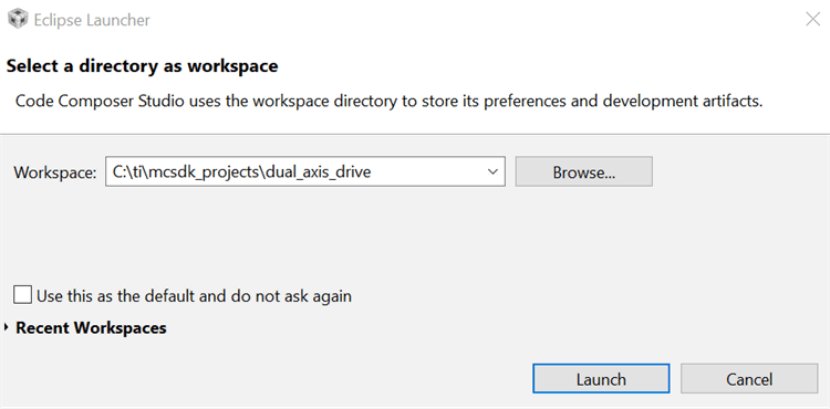 Figure 9. CCS Workspace Launcher
 - This will open a "Getting Started" tab with links to various tasks from creating a new project, importing an existing project to watching a Tutorial on CCS.
- Add the motor control projects into the current workspace by clicking “Project->Import CCS Project”.
- Select the evaluation project by browsing as shown in Figure 10 to: "\ti\c2000\C2000Ware_MotorControl_SDK_<version>\solutions\boostxl_3phganinv\f2837x\ccs\sensored_foc".
- If there are multiple projects in this directory, then click and choose the projects to import. Click Finish. This copies all of the selected projects into the workspace. In Figure 10, there is only one project. Select it and click Finish.
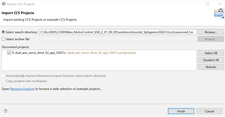 Figure 10. Adding Dual-Axis Drive Project to Workspace
Setting up the Target Configuration
- Configure Code Composer Studio to know which MCU it will be connecting to. This is done by setting up the "Target Configuration". All of these are already set up and configured in “TMS320F28379D.ccxml” provided as part of the files in project. You can skip to step 5, if needed. However, for general information regarding setting up this configuration file, steps 1, 2 and 3 can be used.
- A new configuration file can be set by clicking “File → New- → Target Configuration File" on the menu bar. This will open the Target Configuration window. In this window, give a name to the new configuration file depending on the target device. If “Use shared location” checkbox is checked, then this configuration file can be stored in a common location by CCS for use by other projects as well. Then, click Finish.
- This should open up a new tab as shown in Figure 11. Select and enter the options as shown:
- Connection – Texas Instruments XDS100v2 USB Debug Probe.
- Device – the C2000 MCU on the control card, TMS320F28379D.
- Click Save and close.
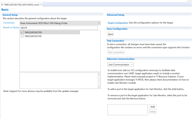 Figure 11. New Target Configuration
 - To use this configuration file, click “View->Target Configurations” on the menu bar. In the “User Defined” section, find the file that was created in step 1, 2 and 3. Right-click on this file and select “Set as Default”.
- To use the configuration file supplied with the project, click “View->Target Configurations", then expand “dual_axis_servo_drive_fcl_qep_f2837x” and right-click on the file “TMS320F28379D.ccxml” and “Set as Default”. This tab also allows you to reuse existing target configurations and link them to specific projects.
Configuring a Project
- The project can be configured to create code and run in either flash or RAM. You may select either of the two, however, for lab experiments use the RAM configuration most of the time and move to the FLASH configuration for production. As shown in Figure 12, right-click on an individual project and select "Build Configurations->Set Active->F2837x_RAM" configuration.
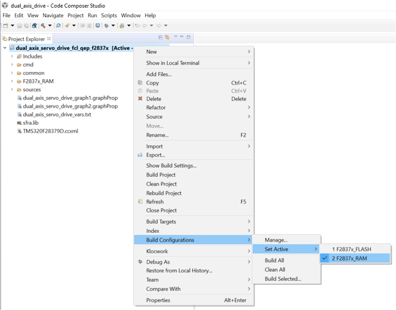 Figure 12. Selecting the F2837x_RAM Configuration
 Build and Load the Project
- The example project is provided with incremental builds where different components / macro blocks of the system are pieced together one by one to form the entire system. This helps in step by step debug and understanding of the system. From the CCS Edit Perspective, open the file "dual_axis_servo_drive_settings.h" and make sure that BUILDLEVEL is set to FCL_LEVEL1.
- Open the "dual_axis_servo_drive.c" file and go to the function motor1ControlISR(). Locate the following piece of code in incremental build FCL_LEVEL1 and confirm that the datalog buffers are pointing to the right variables. These datalog buffers are large arrays that contain value-triggered data that can then be displayed to a graph. Note that in other incremental builds different variables may be put into this buffer to be graphed.
- Now Right Click on the Project Name and click on “Rebuild Project” and watch the Console window. Any errors in the project will be displayed, which needs to be fixed. There may be some warning messages about certain functions or variables not being used. Such warning messages may be ignored, as they may be used in another build level.
Connecting the Hardware to Computer
- Mount BoosterPack BOOSTXL-3PhGaNInv on LaunchPad headers J1-J4. DO NOT connect motor right now. Connect the LaunchPad to computer through an USB cable, this will light some LEDs on the emulator section of LaunchPad, indicating that the emulator is on. Power the BoosterPack with appropriate input dc voltage, 24V. This will glow various LEDs on both BoosterPack and LaunchPad.
- Continuing from step 3 of "Build and Load the Project", on successful completion of the build, click the “Debug” button
 , located in the top-left side of the screen.
 - The IDE will now connect to the target, load the output file into the device and change to the Debug perspective.
- Click “Tools → Debugger Options → Program / Memory Load Options”. You can enable the debugger to reset the processor each time it reloads program by checking “Reset the target on program load or restart” and click “Remember My Settings” to make this setting permanent.
- Now click on the “Enable silicon real-time mode” button
 which also auto selects “Enable polite real-time mode” button
 . This allows you to edit and view variables in real-time. Do not reset the CPU without disabling these real time options!
 - A message box may appear. If so, select "YES" to enable debug events. This will set bit 1 (DGBM bit) of status register 1 (ST1) to a “0”. The DGBM is the debug enable mask bit. When the DGBM bit is set to “0”, memory and register values can be passed to the host processor for updating the debugger windows.
Configuring Expressions Window
- Click "View- → Expressions" on the menu bar to open an Expressions window to view the variables being used in the project. Add variables to the expressions window as shown below. It uses the number format associated with variables during declaration. You can select a desired number format for the variable by right clicking on it and choosing. Figure 13 shows a typical expressions window.
- Alternately, a group of variables can be imported into the Expressions window, by right clicking within Expressions Window and clicking Import, and browse to the .txt file containing these variables. Here, browse to the directory of the project at "\ti\c2000\C2000Ware_MotorControl_SDK_<version>\solutions\common\sensored_foc\debug\" and pick "dual_axis_servo_drive_vars.txt" and click OK to import the variables shown in Figure 14.
- The structure variables 'motorVars[0]' and 'motorVars[1]' have references to all peripherals and variables that are related to controlling dual motor. By expanding this variable, you can see them all and edit as needed.
- Click on the Continuous Refresh button
 in the expressions window. This enables the window to run with real-time mode. By clicking the down arrow in this expressions window, you may select “Customize Continuous Refresh Interval” and edit the refresh rate of the expressions window. Note that choosing too fast an interval may affect performance.
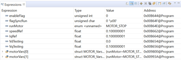 Figure 13. Configuring the Expressions Window
 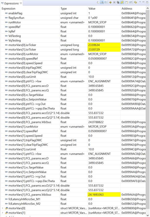 Figure 14. Variables Import for Project
 Setting up Graphs
- The datalog buffers point to different system variables depending on the build level. They provide a means to visually inspect the variables and judge system performance. Open and setup time graph windows to plot the data log buffers as shown below. Alternatively, the graph configurations files can be imported in the project folder by clicking 'Tools → Graph → DualTime" on the menu bar and select import and browse to the following location at "\ti\c2000\C2000Ware_MotorControl_SDK_<version>\solutions\common\sensored_foc\debug" and select "dual_axis_servo_drive_graph1.graphProp", the Graph Properties window should now look like the Figure 15. Click OK, this should add the Graphs to your debug perspective. Click on Continuous Refresh button
 on the top left corner of the graph tab. If there is no real time graph in the window, click the Reset Graph button
 , and then click Continuous Refresh button
  again.
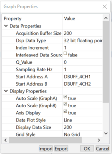 Figure 15. Graph Window Settings
 NOTE
- If a second graph window is used, you could import dual_axis_servo_drive_graph2.graphProp, the start Addresses for this should be DBUFF_4CH3 and DBUFF_4CH4.
- The default 'dlog.prescaler' is set to 5 which will allow the dlog function to only log one out of every five samples.
- The default 'dlog.trig_value' should be set to the right value to generate trigger for the plot as in oscilloscopes.
Run the Code
- Run the code by clicking Run Button
 in the Debug Tab
 - In the Expressions window, set the variable ‘enableFlag’ to 1.
- The project should now run, and the values in the graphs and expressions window should continuously update. Figure 16 and Figure 17 are some screen captures of typical CCS perspectives while using this project. You may want to resize the windows according to your preference. At this time, details of variables and graph are not discussed as they will be discussed in later sections
- Once complete, turn off Real Time mode, then reset the processor (Run->Reset->CPU Reset) and then terminate the debug session by clicking Terminate
 in the Debug Tab. This halts the program and disconnects Code Composer from the MCU.
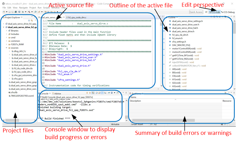 Figure 16. CCS IDE Showing Edit Perspective
 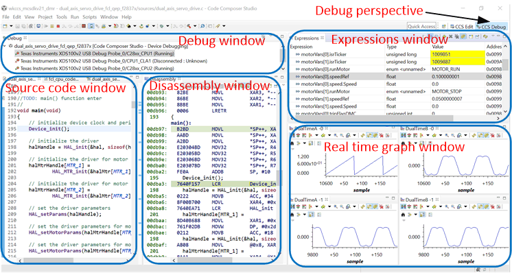 Figure 17. CCS IDE Showing Debug Perspective
 Step 10. Next Operations
- It is not necessary to terminate the debug session each time you change or run the code again. Instead the following procedure can be followed.
- Disable real time options, terminate the project, reset CPU (Run->Reset->CPU Reset) , rebuild and reload the project if changed the code.
- Disable real time options, terminate the project, reset CPU (Run->Reset->CPU Reset) , (Run->Restart ), and enable realtime options if without changing the code.
- Terminate the project if the target device or the configuration is changed (Ram to Flash or Flash to Ram) prior to shutting down CCS.
- The header file "dual_axis_servo_drive_settings.h" and "dual_axis_servo_drive_user.h" in the CCS Edit Perspective has macro definitions for motor control. You can change these parameters as needed after thinking through the impact of such change.
- You can proceed to experiment various build levels in detail.