SPRACP5 December 2019 TMS320F2802-Q1 , TMS320F28020 , TMS320F280200 , TMS320F28021 , TMS320F28022 , TMS320F28022-Q1 , TMS320F280220 , TMS320F28023 , TMS320F28023-Q1 , TMS320F280230 , TMS320F28026 , TMS320F28026-Q1 , TMS320F28026F , TMS320F28027 , TMS320F28027-Q1 , TMS320F280270 , TMS320F28027F , TMS320F28027F-Q1 , TMS320F28030 , TMS320F28030-Q1 , TMS320F28031 , TMS320F28031-Q1 , TMS320F28032 , TMS320F28032-Q1 , TMS320F28033 , TMS320F28033-Q1 , TMS320F28034 , TMS320F28034-Q1 , TMS320F28035 , TMS320F28035-EP , TMS320F28035-Q1 , TMS320F28050 , TMS320F28051 , TMS320F28052 , TMS320F28052-Q1 , TMS320F28052F , TMS320F28052F-Q1 , TMS320F28052M , TMS320F28052M-Q1 , TMS320F28053 , TMS320F28054 , TMS320F28054-Q1 , TMS320F28054F , TMS320F28054F-Q1 , TMS320F28054M , TMS320F28054M-Q1 , TMS320F28055 , TMS320F2806-Q1 , TMS320F28062 , TMS320F28062-Q1 , TMS320F28062F , TMS320F28062F-Q1 , TMS320F28063 , TMS320F28064 , TMS320F28065 , TMS320F28066 , TMS320F28066-Q1 , TMS320F28067 , TMS320F28067-Q1 , TMS320F28068F , TMS320F28068M , TMS320F28069 , TMS320F28069-Q1 , TMS320F28069F , TMS320F28069F-Q1 , TMS320F28069M , TMS320F28069M-Q1
4.1 Differential Non-Linearity Error
DNL error can be described as the difference in the output code width with regards to an ideal code width, which corresponds to 1 LSB. For the F2803x devices, the DNL error is categorized as ± 1 LSB for an ADC operating at 30 MHz or below. For higher frequencies there might be missing codes depending on the operational conditions (represented by a DNL value of -1). Missing codes indicate that one or more of the possible digital codes is never output. For more details on missing codes, see the TMS320F2803x MCUs Silicon Errata.
NOTE
For the purpose of this analysis, the histogram method was used to calculate the DNL error. For more information on this method, see Section B.
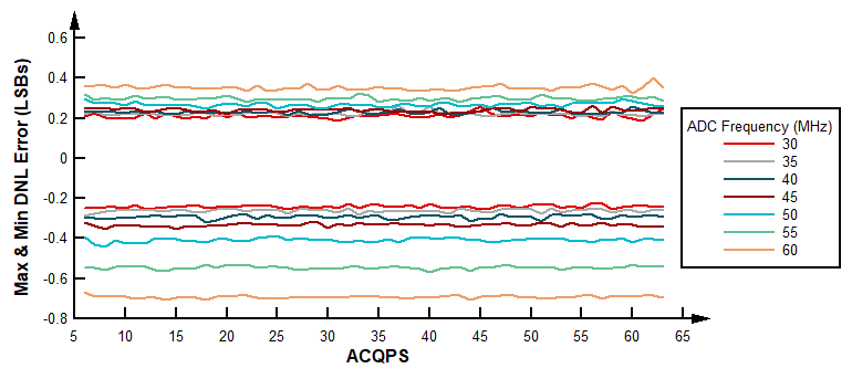
DNL can be represented by two values, the largest of the DNL errors found within all output codes, Max DNL, and the smallest, Min DNL. This report will discuss DNL in these terms for each ACQPS value.
Both in overlap and non-overlap mode, operating the ADC at high frequencies and high temperatures causes larger bounds of error for Max and Min DNL. As can be seen in Figure 9 and Figure 10 there is less DNL error when operating at 30MHz. As the temperature is increased, the range of error between frequencies increases, in ascending order, ultimately leading to larger Max and Min DNL errors. Specifically in overlap mode, missing codes are seen for non-valid ACQPS values at high frequencies. Thus, the higher the frequency, the larger the chances become of missing an output code.
Better performance is seen with higher VDDA voltages. The disparity between error at different frequencies decreases, applicable across all temperatures. However, there are certain ACQPS values that are more susceptible to larger DNL error when VDDA is set to the lowest operational voltage. These effects are exasperated by higher ADC operational frequencies. For the susceptible ACQPS values at the lowest operable VDDA voltage, see Table 2.
Table 2. ACQPS Values Susceptible to High Linearity Error at Minimum VDDA
| Overlap Mode | Non-Overlap Mode |
|---|---|
| {11, 24, 37, 50, 63} | {17, 30, 43, 56} |

