SPRACP5 December 2019 TMS320F2802-Q1 , TMS320F28020 , TMS320F280200 , TMS320F28021 , TMS320F28022 , TMS320F28022-Q1 , TMS320F280220 , TMS320F28023 , TMS320F28023-Q1 , TMS320F280230 , TMS320F28026 , TMS320F28026-Q1 , TMS320F28026F , TMS320F28027 , TMS320F28027-Q1 , TMS320F280270 , TMS320F28027F , TMS320F28027F-Q1 , TMS320F28030 , TMS320F28030-Q1 , TMS320F28031 , TMS320F28031-Q1 , TMS320F28032 , TMS320F28032-Q1 , TMS320F28033 , TMS320F28033-Q1 , TMS320F28034 , TMS320F28034-Q1 , TMS320F28035 , TMS320F28035-EP , TMS320F28035-Q1 , TMS320F28050 , TMS320F28051 , TMS320F28052 , TMS320F28052-Q1 , TMS320F28052F , TMS320F28052F-Q1 , TMS320F28052M , TMS320F28052M-Q1 , TMS320F28053 , TMS320F28054 , TMS320F28054-Q1 , TMS320F28054F , TMS320F28054F-Q1 , TMS320F28054M , TMS320F28054M-Q1 , TMS320F28055 , TMS320F2806-Q1 , TMS320F28062 , TMS320F28062-Q1 , TMS320F28062F , TMS320F28062F-Q1 , TMS320F28063 , TMS320F28064 , TMS320F28065 , TMS320F28066 , TMS320F28066-Q1 , TMS320F28067 , TMS320F28067-Q1 , TMS320F28068F , TMS320F28068M , TMS320F28069 , TMS320F28069-Q1 , TMS320F28069F , TMS320F28069F-Q1 , TMS320F28069M , TMS320F28069M-Q1
4.2 Integral Non-Linearity Error
INL represents the deviation of the values on the ADC’s transfer function from the ideal. Each output code has an INL error that can be described as the summation of all DNL errors leading up that particular output code. The data sheet for the F2803x devices categorizes INL error to be within a ± 4 LSB range for an ADC operating at 30 MHz or below. Equation 1 is used to find the INL error of each output code.
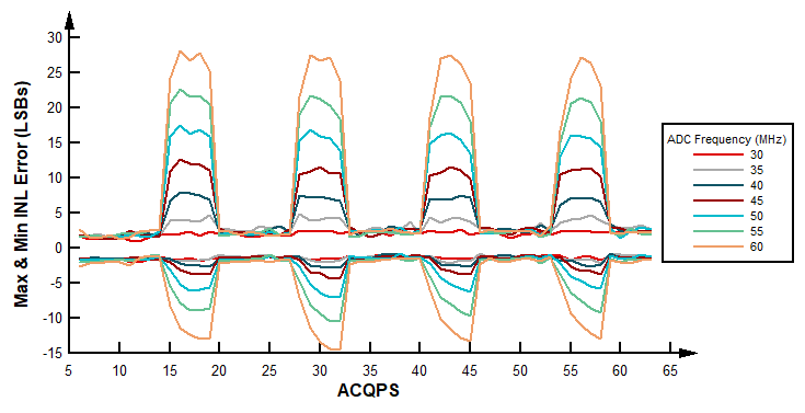
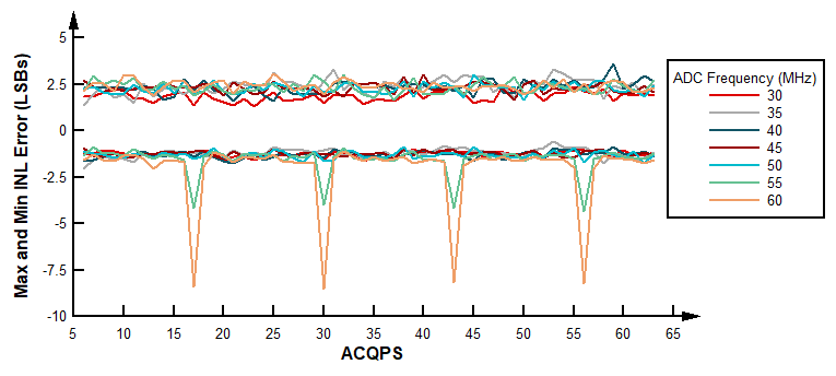
In overlap mode, higher ADC frequencies result in a larger Max and Min INL error for non-valid ACQPS values, seen in Figure 11. The same type of curve applies at all tested temperatures and voltages. In the case of non-overlap mode, the INL error does not vary from operational conditions as much as in overlap mode. For both modes, the error is larger at higher temperatures than the nominal, 30 °C, when operating at higher ADC frequencies. This is applicable to all ACQPS values, but predominantly with the non-valid values. For more details on this subject, see the DC Specifications advisory within the TMS320F2803x MCUs Silicon Errata.

In regards to voltage conditions, performance does not vary with VDDA voltages for valid ACQPS values. However, for non-valid values the linearity error is minimized by decreasing the voltage. Note that when VDDA is set to the minimum value, Table 2 still applies. Figure 12 shows an example of these large spikes of INL error in non-overlap mode when VDDA is set to the minimum value for the ACQPS values not listed in Table 1.
