SPRACP6 December 2019 TMS320F2800132 , TMS320F2800133 , TMS320F2800135 , TMS320F2800137 , TMS320F2800152-Q1 , TMS320F2800153-Q1 , TMS320F2800154-Q1 , TMS320F2800155 , TMS320F2800155-Q1 , TMS320F2800156-Q1 , TMS320F2800157 , TMS320F2800157-Q1 , TMS320F280021 , TMS320F280021-Q1 , TMS320F280023 , TMS320F280023-Q1 , TMS320F280023C , TMS320F280025 , TMS320F280025-Q1 , TMS320F280025C , TMS320F280025C-Q1 , TMS320F280040-Q1 , TMS320F280040C-Q1 , TMS320F280041 , TMS320F280041-Q1 , TMS320F280041C , TMS320F280041C-Q1 , TMS320F280045 , TMS320F280048-Q1 , TMS320F280048C-Q1 , TMS320F280049 , TMS320F280049-Q1 , TMS320F280049C , TMS320F280049C-Q1
- How to Maximize GPIO Usage in C2000 Devices
6 AIO Option
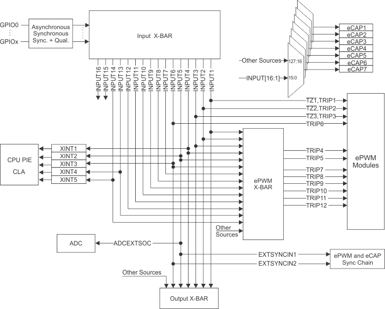
The analog signals in the F28004x device are multiplexed with digital input functionality. In the F28004x device, the Input X-BAR has access to every GPIO, including AIOs, so Input X-BAR can be used to route signals from a GPIO to many different IP blocks such as the ADC(s), eCAP(s), ePWM(s), and external interrupts, as shown in Figure 3.
 Figure 3. Input X-BAR
 For example, the following code outlines using a digital AIO to receive Fault IO signal, then to trigger ePWM protection actions. As shown in Table 4, ADC B5 channel refers to AIO243. In this example, both Input X-BAR and ePWM X-BAR will be used.
Table 4. AIO Pins Mapping
| Analog Group 4 | CMP4 | |||||||||||
|---|---|---|---|---|---|---|---|---|---|---|---|---|
| B5 | G4_ADCAB | B5 | HPMXSEL = 3 | HNMXSEL = 0 | LPMXSEL = 3 | LNMXSEL = 0 | AIO243 | |||||
| B4/C8/PGA4_OF | PGA4_OF | 39 | 24 | 22 | B4 | C8 | PGA4_OF | HPMXSEL = 0 | LPMXSEL = 0 | AIO227 | ||
| C3 | G4_ADCC | C3 | HPMXSEL = 1 | HNMXSEL = 1 | LPMXSEL = 1 | LNMXSEL = 1 | AIO245 | |||||
| PGA4_IN | PGA4_IN | PGA4_IN | HPMXSEL = 2 | LPMXSEL = 2 | ||||||||
| PGA4_GND | PGA4_GND | 32 | 20 | 18 | PGA4_GND | |||||||
| - | PGA4_OUT | B11 | C9 | PGA4_OUT | HPMXSEL = 4 | LPMXSEL = 4 | ||||||
// enable digital mode for AIO243(B5)
    GPIO_setAnalogMode(243, GPIO_ANALOG_DISABLED);
    GPIO_setPinConfig(GPIO_243_GPIO243);
    GPIO_setDirectionMode(243, GPIO_DIR_MODE_IN);
    GPIO_setPadConfig(234U, GPIO_PIN_TYPE_STD);

    //Configure AIO243 as INPUT X-BAR 1
   XBAR_setInputPin(XBAR_INPUT1, 243);

   // Configure INPUT X-BAR 1 as EPWM X-BAR TRIP4
    XBAR_setEPWMMuxConfig(XBAR_TRIP4, XBAR_EPWM_MUX01_INPUTXBAR1);
    XBAR_enableEPWMMux(XBAR_TRIP4, XBAR_MUX01);

//To see the remainder of the code, refer to the example in C:\ti\c2000\C2000Ware__<version_number>\\driverlib\f28004x\examples\cmpss\cmpss_ex1_asynch
Since the AIOs share the same reference as other analog peripherals, if digital signals with sharp edges (high dv/dt) are connected to the AIOs, cross-talk might occur with adjacent analog signals. Therefore, you should limit the edge rate of signals connected to AIOs, so it is suggested to use series resistors at the driver input to an AIO to slow down the edge rate and reduce the coupling. It is also recommended the AIOs be used for signals with minimal toggling, like a FAULT indicator. The AIO input circuit ground pin should be connected to the analog ground VSSA of F28004x.
These analog I/O (AIO) pins do not have digital output capability. For 100-pin PZ package, there are to up to 21 AIOs that share the same pins with ADC channels. They are assigned to a single port: Port H of GPIO224-GPIO247.