SPRACR2 March 2020 TMS320F280021 , TMS320F280021-Q1 , TMS320F280023 , TMS320F280023-Q1 , TMS320F280023C , TMS320F280025 , TMS320F280025-Q1 , TMS320F280025C , TMS320F280025C-Q1
- Enabling Peripheral Expansion Applications Using the HIC
- A Address Translation for Different Data Width Modes
2.5.1 Device Internal Events
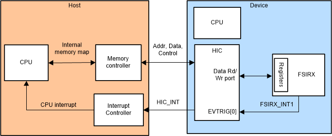
The HIC_INT port can be directly triggered through the EVENTRIG bus by supported peripherals as listed in the Event Trigger Sources table under the HIC chapter in the device-specific technical reference manual. For example, the FSI receiver can be configured to trigger an interrupt event (FSIRX_INT1) on a data tag match and this event can be enabled to generate a HIC_INT to the Host by enabling the corresponding HICD2HINTEN.EVTRIG bit. If the HIC_INT line is connected to an interrupt capable input pin of the Host, the FSI receiver can generate a direct interrupt to the Host CPU whenever there is a data tag match on the received data, thereby eliminating any intervention from the Device CPU.
Using the Device internal interrupt mapping capability and the direct Device access mode, the Host can access the peripheral of interest (that are accessible through the HIC) as if it is available on its own memory map with interrupts mapped directly to its CPU. This is depicted in Figure 8.
 Figure 8. Device Internal Event Usage Model Using FSI