SPRACR2 March 2020 TMS320F280021 , TMS320F280021-Q1 , TMS320F280023 , TMS320F280023-Q1 , TMS320F280023C , TMS320F280025 , TMS320F280025-Q1 , TMS320F280025C , TMS320F280025C-Q1
- Enabling Peripheral Expansion Applications Using the HIC
- A Address Translation for Different Data Width Modes
4.1 Test Setup
Table 6 captures the HIC and EMIF configuration used in the example. The total number of pins required for this configuration is 19.
Table 6. Device and Host Configurations for Pin Constrained Applications
| HIC Configuration | EMIF Configuration |
|---|---|
| Access type: Mailbox mode | Access Type: Select strobe |
| Data width: 8-bit mode | ASIZE: 8-bit data bus |
| Read/write: Single pin |
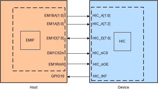
Figure 10 shows the hardware connections required for the example. The access type used in this example is mailbox mode and hence the HIC_nRDY and HIC_BASESEL pins are not connected. Also, since the data width mode is set to 8, the byte enables are not required.
 Figure 10. Hardware Setup for the Example hic_ex2_config_8bit_adc