SPRACR2 March 2020 TMS320F280021 , TMS320F280021-Q1 , TMS320F280023 , TMS320F280023-Q1 , TMS320F280023C , TMS320F280025 , TMS320F280025-Q1 , TMS320F280025C , TMS320F280025C-Q1
- Enabling Peripheral Expansion Applications Using the HIC
- A Address Translation for Different Data Width Modes
5.1 Test Setup
Table 7 captures the HIC and EMIF configuration used in the example. The total number of pins required for this configuration is 32.
Table 7. Device and Host Configurations for Performance-Critical applications
| HIC Configuration | EMIF Configuration |
|---|---|
| Access type: Direct access mode | Access Type: Normal mode |
| Data width: 16-bit mode | ASIZE: 16-bit data bus |
| Read/write: Dual pin | |
| Pagesel type: Register selection |
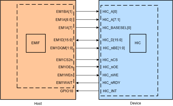
Figure 11 shows the hardware connections required for the example. The access type used in this example is direct access mode and hence the HIC_nRDY and HIC_BASEL0 pins are required to be connected. Also, the byte enables are connected to perform 8-bit accesses in the 16-bit data width mode. Note that dual pin read/write mode is chosen in the example to cover the variety of configurations and is not a mandate mode for higher performance.
 Figure 11. Hardware Setup for the Example hic_ex2_config_16bit_fsi