SPRACR6 April 2020 F29H850TU , F29H859TU-Q1 , TMS320F280023-Q1 , TMS320F280023C , TMS320F280025C , TMS320F280025C-Q1 , TMS320F280041-Q1 , TMS320F280041C , TMS320F280041C-Q1 , TMS320F280048-Q1 , TMS320F280048C-Q1 , TMS320F280049-Q1 , TMS320F280049C , TMS320F280049C-Q1 , TMS320F28384D , TMS320F28384D-Q1 , TMS320F28384S , TMS320F28384S-Q1 , TMS320F28386D , TMS320F28386D-Q1 , TMS320F28386S , TMS320F28386S-Q1 , TMS320F28388D , TMS320F28388S , TMS320F28P650DH , TMS320F28P650DK , TMS320F28P650SH , TMS320F28P650SK , TMS320F28P659DH-Q1 , TMS320F28P659DK-Q1 , TMS320F28P659SH-Q1
3.1 MPPT DC/DC Stage
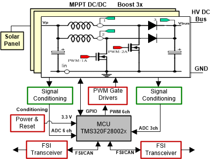
Figure 7 illustrates a C2000-based MPPT DC-DC converter control used in solar string inverter application. PV panel output voltage, Vp, is applied to the DC/DC input stage. This DC/DC stage illustrates conventional 2 phase interleaved boost topology.
 Figure 7. MPPT DC/DC Boost Control Using C2000 MCU
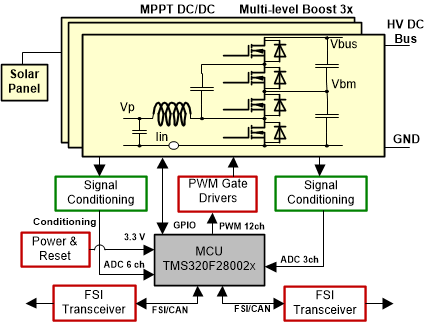
 Figure 8 shows the same MPPT DC/DC control using a 3 level boost topology. In both cases three boost stages are shown to be configured in parallel and controlled by the same C2000 MCU. Both the figures show the specific controller used in this case is TMS320F28002x series MCUs. Figure 7 and Figure 8 indicate all the interface signals needed for full control of this DC-DC converter using a F28002x MCU. The MCU controls each boost stage using three feedback signals and two PWM (Figure 7) or four PWM (Figure 8) outputs. The sensed signals are, panel output voltage (Vp), the boost output voltage (Vbus) and the total boost inductor currents (Iin). These sensed signals are used to implement the voltage and current control loops for the DC-DC stage.
 Figure 8. MPPT Multi-Level DC/DC Boost Control Using C2000 MCU
 Figure 9 shows the boost converter control loops. This uses the current mode control. However, the goal is to control the PV panel output (Vp) that is the input to the DC-DC stage. This allows the PV panel (array) operates at its maximum power point at all time. Input voltage Vp is regulated by adjusting the input current Iin. A Maximum Power Point Tracking (MPPT) algorithm determines the set point (Vp_ref) for the PV panel voltage.
 Figure 9. MPPT DC-DC Converter Control Loops
 Table 1 shows the number of F28002x MCU needed to support different configurations of MPPT DC/DC boost stages shown in Figure 9. For example, to control 12 boost stages, shown in Figure 8, a total of four F28002x MCUs are needed. This is because 12 boost stages require 48 PWM and 36 ADC channels and the four F28002x MCUs provide 56 PWM and 64 ADC channels. Thus, the number of spare PWM and ADC channels for such a configuration will be, 8 and 28, respectively. This is also listed as the last two row entries in Table 1. The last two column entries in Table 1 also show the F28002x MCU requirements for controlling 16 and 24 MPPT DC/DC boost stages. For 16 MPPT stages, five F28002x MCUs are needed. For 24 MPPT stages, the number of F28002x MCUs needed will be 7.
Table 1. MPPT DC/DC Boost Stages vs Number of F28002x MCU
| MPPT-12 Boost Stages | MPPT-16 Boost Stages | MPPT-24 Boost Stages | |
|---|---|---|---|
| # PWM channels needed | 48 | 64 | 96 |
| # ADC channels needed | 36 | 48 | 72 |
| #F28002x MCU needed | 4 | 5 | 7 |
| Spare PWM channels available for nBoosts configuration | 8 | 6 | 2 |
| Spare ADC channels available for nBoosts configuration | 28 | 32 | 40 |