SPRACY7 October 2021 TMS320F2800132 , TMS320F2800133 , TMS320F2800135 , TMS320F2800137 , TMS320F2800152-Q1 , TMS320F2800153-Q1 , TMS320F2800154-Q1 , TMS320F2800155 , TMS320F2800155-Q1 , TMS320F2800156-Q1 , TMS320F2800157 , TMS320F2800157-Q1 , TMS320F280033 , TMS320F280034 , TMS320F280034-Q1 , TMS320F280036-Q1 , TMS320F280036C-Q1 , TMS320F280037 , TMS320F280037-Q1 , TMS320F280037C , TMS320F280037C-Q1 , TMS320F280038-Q1 , TMS320F280038C-Q1 , TMS320F280039 , TMS320F280039-Q1 , TMS320F280039C , TMS320F280039C-Q1
3.2 Generate Serial Data With Rotate Mode
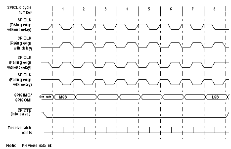
The SIGGEN module can operate in ROTATE RIGHT ONCE mode. This mode can be used to generate both serial data and serial clock signals. This example will generate the serial clock and serial data signals, similar to the SPI module. The SPI clock and data signals can be generated in four possible modes.
 Figure 3-6 SPI Modes
All different modes of the SPICLK and SPI data can be generated by the EPG SIGGEN module. Table 3-1 maps the name of the SPICLK mode with the SPI clock polarity and phase modes.
| SPICLK Mode | SPI Clock Phase and Polarity |
|---|---|
| Rising edge without delay | CPOL=0, CPHA=0 |
| Rising edge with delay | CPOL=0, CPHA=1 |
| Falling edge without delay | CPOL=1, CPHA=0 |
| Falling edge with delay | CPOL=1, CPHA=1 |
Both the SPICLK and SPI data are generated by the SIGGEN module. The SIGGEN module will be clocked by the CLKGEN module. Similar to the previous example, the frequency of the SPICLK generated will depend on the CLKGEN period and the SIGGEN BIT-LENGTH. In this example, the CLKGEN period is set to 10 (meaning EPGCLK/10) and the BIT-LENGTH of the SIGGEN module is set 16.
With a BIT-LENGTH of 16, the SIGGEN module can generate SPICLK and SPI data signals which can output an 8-bit word on the GPIO. SIGGEN module requires a minimum BIT-LENGTH of 16 to be able place SPICLK edges between the generated SPI data. In this example, rotate right once mode is used. The same signals can be generated through the SHIFT RIGHT ONCE mode as well (explored in the next section).