SPRADE8 November 2023 TMS320F28P650DH , TMS320F28P650DK , TMS320F28P650SH , TMS320F28P650SK , TMS320F28P659DH-Q1 , TMS320F28P659DK-Q1 , TMS320F28P659SH-Q1
- EEPROM Emulation for Generation 3 C2000 Real Time Controllers
- Trademarks
- 1 Introduction
- 2 Difference Between EEPROM and On-Chip Flash
- 3 Overview
- 4 Software Description
-
5 Ping-Pong Emulation
- 5.1 User-Configuration
- 5.2
EEPROM Functions
- 5.2.1 EEPROM_Config_Check
- 5.2.2 Configure_Protection_Masks
- 5.2.3 EEPROM_Write
- 5.2.4 EEPROM_Read
- 5.2.5 EEPROM_Erase
- 5.2.6 EEPROM_GetValidBank
- 5.2.7 EEPROM_UpdateBankStatus
- 5.2.8 EEPROM_UpdatePageStatus
- 5.2.9 EEPROM_Get_64_Bit_Data_Address
- 5.2.10 EEPROM_Program_64_Bits
- 5.2.11 EEPROM_CheckStatus
- 5.2.12 ClearFSMStatus
- 5.3 Testing Example
-
6 Single-Unit Emulation
- 6.1 User-Configuration
- 6.2
EEPROM Functions
- 6.2.1 EEPROM_Config_Check
- 6.2.2 Configure_Protection_Masks
- 6.2.3 EEPROM_Write
- 6.2.4 EEPROM_Erase
- 6.2.5 EEPROM_GetValidBank
- 6.2.6 EEPROM_Get_64_Bit_Data_Address
- 6.2.7 EEPROM_UpdateBankStatus
- 6.2.8 EEPROM_UpdatePageStatus
- 6.2.9 EEPROM_Get_64_Bit_Data_Address
- 6.2.10 EEPROM_Program_64_Bits
- 6.2.11 EEPROM_CheckStatus
- 6.2.12 ClearFSMStatus
- 6.3 Testing Example
- 7 Application Integration
- 8 Adapting to Other Gen 3 C2000 MCUs
- 9 Flash API
- 10Source File Listing
- 11Conclusion
- 12References
3.3 Ping-Pong Method
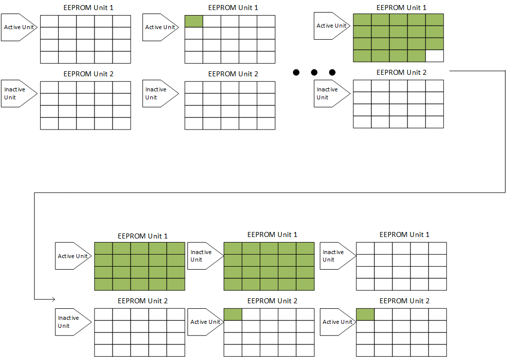
If using the Ping Pong method, the following diagram shows the implemented behavior. As shown in Figure 3-2, there are two EEPROM units made up of selected Flash Sectors. One is marked as an Active Unit, and the other is marked as the Inactive Unit. To begin, data is written to the Active Unit.
 Figure 3-2 Ping Pong Behavior
If the Active Unit is full and there is more data to be written, the Active and Inactive EEPROM units will switch. Therefore, the previously Active Unit (full Unit) will be marked as Inactive, and the previously Inactive Unit (empty Unit) will be marked as Active. Subsequently, the data will be written to the newly Active EEPROM Unit. After the data is successfully programmed to the Active EEPROM Unit, the Inactive EEPROM Unit is erased. This method ensures that there is a fall-back options for the last successfully written data in case of any failure during the erase or program operation when the currently active EEPROM Unit is full.
This process can be repeated as necessary.