SPRUHM9H October 2014 – May 2024 TMS320F28075 , TMS320F28075-Q1 , TMS320F28076
- 1
- Read This First
- 1 C2000™ Microcontrollers Software Support
- 2 C28x Processor
-
3 System Control and Interrupt
- 3.1 Introduction
- 3.2 System Control Functional Description
- 3.3
Resets
- 3.3.1 Reset Sources
- 3.3.2 External Reset (XRS)
- 3.3.3 Power-On Reset (POR)
- 3.3.4 Debugger Reset (SYSRS)
- 3.3.5 Watchdog Reset (WDRS)
- 3.3.6 NMI Watchdog Reset (NMIWDRS)
- 3.3.7 DCSM Safe Code Copy Reset (SCCRESET)
- 3.3.8 Hibernate Reset (HIBRESET)
- 3.3.9 Hardware BIST Reset (HWBISTRS)
- 3.3.10 Test Reset (TRST)
- 3.4 Peripheral Interrupts
- 3.5 Exceptions and Non-Maskable Interrupts
- 3.6 Safety Features
- 3.7 Clocking
- 3.8 32-Bit CPU Timers 0/1/2
- 3.9 Watchdog Timers
- 3.10 Low-Power Modes
- 3.11
Memory Controller Module
- 3.11.1
Functional Description
- 3.11.1.1 Dedicated RAM (Dx RAM)
- 3.11.1.2 Local Shared RAM (LSx RAM)
- 3.11.1.3 Global Shared RAM (GSx RAM)
- 3.11.1.4 Message RAM (CLA MSGRAM)
- 3.11.1.5 Access Arbitration
- 3.11.1.6 Access Protection
- 3.11.1.7 Memory Error Detection, Correction and Error Handling
- 3.11.1.8 Application Test Hooks for Error Detection and Correction
- 3.11.1.9 RAM Initialization
- 3.11.1
Functional Description
- 3.12
Flash and OTP Memory
- 3.12.1 Features
- 3.12.2 Flash Tools
- 3.12.3 Default Flash Configuration
- 3.12.4 Flash Bank, One-Time Programmable (OTP) Memory, and Flash Pump
- 3.12.5 Flash Module Controller (FMC)
- 3.12.6 Flash and OTP Memory Power-Down Modes and Wakeup
- 3.12.7 Flash and OTP Memory Performance
- 3.12.8 Flash Read Interface
- 3.12.9 Erase/Program Flash
- 3.12.10 Error Correction Code (ECC) Protection
- 3.12.11 Reserved Locations Within Flash and OTP Memory
- 3.12.12 Procedure to Change the Flash Control Registers
- 3.12.13 Simple Procedure to Modify an Application from RAM Configuration to Flash Configuration
- 3.13
Dual Code Security Module (DCSM)
- 3.13.1 Functional Description
- 3.13.2 CSM Impact on Other On-Chip Resources
- 3.13.3
Incorporating Code Security in User Applications
- 3.13.3.1 Environments That Require Security Unlocking
- 3.13.3.2 CSM Password Match Flow
- 3.13.3.3 Unsecuring Considerations for Zones With and Without Code Security
- 3.13.3.4 Environments That Require ECSL Unlocking
- 3.13.3.5 ECSL Password Match Flow
- 3.13.3.6 ECSL Disable Considerations for any Zone
- 3.13.3.7 Device Unique ID
- 3.14 JTAG
- 3.15 System Control Register Configuration Restrictions
- 3.16 Software
- 3.17
System Control Registers
- 3.17.1 System Control Base Addresses
- 3.17.2 CPUTIMER_REGS Registers
- 3.17.3 PIE_CTRL_REGS Registers
- 3.17.4 WD_REGS Registers
- 3.17.5 NMI_INTRUPT_REGS Registers
- 3.17.6 XINT_REGS Registers
- 3.17.7 SYNC_SOC_REGS Registers
- 3.17.8 DMA_CLA_SRC_SEL_REGS Registers
- 3.17.9 DEV_CFG_REGS Registers
- 3.17.10 CLK_CFG_REGS Registers
- 3.17.11 CPU_SYS_REGS Registers
- 3.17.12 ROM_PREFETCH_REGS Registers
- 3.17.13 DCSM_Z1_REGS Registers
- 3.17.14 DCSM_Z2_REGS Registers
- 3.17.15 DCSM_COMMON_REGS Registers
- 3.17.16 MEM_CFG_REGS Registers
- 3.17.17 ACCESS_PROTECTION_REGS Registers
- 3.17.18 MEMORY_ERROR_REGS Registers
- 3.17.19 ROM_WAIT_STATE_REGS Registers
- 3.17.20 FLASH_CTRL_REGS Registers
- 3.17.21 FLASH_ECC_REGS Registers
- 3.17.22 UID_REGS Registers
- 3.17.23 DCSM_Z1_OTP Registers
- 3.17.24 DCSM_Z2_OTP Registers
- 3.17.25
Register to Driverlib Function Mapping
- 3.17.25.1 CPUTIMER Registers to Driverlib Functions
- 3.17.25.2 ASYSCTL Registers to Driverlib Functions
- 3.17.25.3 PIE Registers to Driverlib Functions
- 3.17.25.4 SYSCTL Registers to Driverlib Functions
- 3.17.25.5 NMI Registers to Driverlib Functions
- 3.17.25.6 XINT Registers to Driverlib Functions
- 3.17.25.7 DCSM Registers to Driverlib Functions
- 3.17.25.8 MEMCFG Registers to Driverlib Functions
- 3.17.25.9 FLASH Registers to Driverlib Functions
-
4 ROM Code and Peripheral Booting
- 4.1 Introduction
- 4.2 Boot ROM Registers
- 4.3 Device Boot Sequence
- 4.4 Device Boot Modes
- 4.5 Configuring Boot Mode Pins
- 4.6 Configuring Get Boot Options
- 4.7 Configuring Emulation Boot Options
- 4.8 Device Boot Flow Diagrams
- 4.9 Device Reset and Exception Handling
- 4.10 Boot ROM Description
- 5 Direct Memory Access (DMA)
-
6 Control Law Accelerator (CLA)
- 6.1 Introduction
- 6.2 CLA Interface
- 6.3 CLA and CPU Arbitration
- 6.4 CLA Configuration and Debug
- 6.5 Pipeline
- 6.6 Software
- 6.7
Instruction Set
- 6.7.1 Instruction Descriptions
- 6.7.2 Addressing Modes and Encoding
- 6.7.3
Instructions
- MABSF32 MRa, MRb
- MADD32 MRa, MRb, MRc
- MADDF32 MRa, #16FHi, MRb
- MADDF32 MRa, MRb, #16FHi
- MADDF32 MRa, MRb, MRc
- MADDF32 MRd, MRe, MRf||MMOV32 mem32, MRa
- MADDF32 MRd, MRe, MRf ||MMOV32 MRa, mem32
- MAND32 MRa, MRb, MRc
- MASR32 MRa, #SHIFT
- MBCNDD 16BitDest [, CNDF]
- MCCNDD 16BitDest [, CNDF]
- MCMP32 MRa, MRb
- MCMPF32 MRa, MRb
- MCMPF32 MRa, #16FHi
- MDEBUGSTOP
- MEALLOW
- MEDIS
- MEINVF32 MRa, MRb
- MEISQRTF32 MRa, MRb
- MF32TOI16 MRa, MRb
- MF32TOI16R MRa, MRb
- MF32TOI32 MRa, MRb
- MF32TOUI16 MRa, MRb
- MF32TOUI16R MRa, MRb
- MF32TOUI32 MRa, MRb
- MFRACF32 MRa, MRb
- MI16TOF32 MRa, MRb
- MI16TOF32 MRa, mem16
- MI32TOF32 MRa, mem32
- MI32TOF32 MRa, MRb
- MLSL32 MRa, #SHIFT
- MLSR32 MRa, #SHIFT
- MMACF32 MR3, MR2, MRd, MRe, MRf ||MMOV32 MRa, mem32
- MMAXF32 MRa, MRb
- MMAXF32 MRa, #16FHi
- MMINF32 MRa, MRb
- MMINF32 MRa, #16FHi
- MMOV16 MARx, MRa, #16I
- MMOV16 MARx, mem16
- MMOV16 mem16, MARx
- MMOV16 mem16, MRa
- MMOV32 mem32, MRa
- MMOV32 mem32, MSTF
- MMOV32 MRa, mem32 [, CNDF]
- MMOV32 MRa, MRb [, CNDF]
- MMOV32 MSTF, mem32
- MMOVD32 MRa, mem32
- MMOVF32 MRa, #32F
- MMOVI16 MARx, #16I
- MMOVI32 MRa, #32FHex
- MMOVIZ MRa, #16FHi
- MMOVZ16 MRa, mem16
- MMOVXI MRa, #16FLoHex
- MMPYF32 MRa, MRb, MRc
- MMPYF32 MRa, #16FHi, MRb
- MMPYF32 MRa, MRb, #16FHi
- MMPYF32 MRa, MRb, MRc||MADDF32 MRd, MRe, MRf
- MMPYF32 MRd, MRe, MRf ||MMOV32 MRa, mem32
- MMPYF32 MRd, MRe, MRf ||MMOV32 mem32, MRa
- MMPYF32 MRa, MRb, MRc ||MSUBF32 MRd, MRe, MRf
- MNEGF32 MRa, MRb[, CNDF]
- MNOP
- MOR32 MRa, MRb, MRc
- MRCNDD [CNDF]
- MSETFLG FLAG, VALUE
- MSTOP
- MSUB32 MRa, MRb, MRc
- MSUBF32 MRa, MRb, MRc
- MSUBF32 MRa, #16FHi, MRb
- MSUBF32 MRd, MRe, MRf ||MMOV32 MRa, mem32
- MSUBF32 MRd, MRe, MRf ||MMOV32 mem32, MRa
- MSWAPF MRa, MRb [, CNDF]
- MTESTTF CNDF
- MUI16TOF32 MRa, mem16
- MUI16TOF32 MRa, MRb
- MUI32TOF32 MRa, mem32
- MUI32TOF32 MRa, MRb
- MXOR32 MRa, MRb, MRc
- 6.8 CLA Registers
- 7 General-Purpose Input/Output (GPIO)
- 8 Crossbar (X-BAR)
- 9 Analog Subsystem
-
10Analog-to-Digital Converter (ADC)
- 10.1 Introduction
- 10.2 ADC Configurability
- 10.3 SOC Principle of Operation
- 10.4 SOC Configuration Examples
- 10.5 ADC Conversion Priority
- 10.6 Burst Mode
- 10.7 EOC and Interrupt Operation
- 10.8 Post-Processing Blocks
- 10.9 Opens/Shorts Detection Circuit (OSDETECT)
- 10.10 Power-Up Sequence
- 10.11 ADC Calibration
- 10.12 ADC Timings
- 10.13 Additional Information
- 10.14
Software
- 10.14.1
ADC Examples
- 10.14.1.1 ADC Software Triggering
- 10.14.1.2 ADC ePWM Triggering
- 10.14.1.3 ADC Temperature Sensor Conversion
- 10.14.1.4 ADC Synchronous SOC Software Force (adc_soc_software_sync)
- 10.14.1.5 ADC Continuous Triggering (adc_soc_continuous)
- 10.14.1.6 ADC PPB Offset (adc_ppb_offset)
- 10.14.1.7 ADC PPB Limits (adc_ppb_limits)
- 10.14.1.8 ADC PPB Delay Capture (adc_ppb_delay)
- 10.14.1.9 ADC ePWM Triggering Multiple SOC
- 10.14.1.10 ADC Burst Mode
- 10.14.1.11 ADC Burst Mode Oversampling
- 10.14.1.12 ADC SOC Oversampling
- 10.14.1.13 ADC PPB PWM trip (adc_ppb_pwm_trip)
- 10.14.1
ADC Examples
- 10.15 ADC Registers
- 11Buffered Digital-to-Analog Converter (DAC)
- 12Comparator Subsystem (CMPSS)
- 13Sigma Delta Filter Module (SDFM)
-
14Enhanced Pulse Width Modulator (ePWM)
- 14.1 Introduction
- 14.2 Configuring Device Pins
- 14.3 ePWM Modules Overview
- 14.4
Time-Base (TB) Submodule
- 14.4.1 Purpose of the Time-Base Submodule
- 14.4.2 Controlling and Monitoring the Time-Base Submodule
- 14.4.3 Calculating PWM Period and Frequency
- 14.4.4 Phase Locking the Time-Base Clocks of Multiple ePWM Modules
- 14.4.5 Simultaneous Writes to TBPRD and CMPx Registers Between ePWM Modules
- 14.4.6 Time-Base Counter Modes and Timing Waveforms
- 14.4.7 Global Load
- 14.5 Counter-Compare (CC) Submodule
- 14.6 Action-Qualifier (AQ) Submodule
- 14.7 Dead-Band Generator (DB) Submodule
- 14.8 PWM Chopper (PC) Submodule
- 14.9 Trip-Zone (TZ) Submodule
- 14.10 Event-Trigger (ET) Submodule
- 14.11 Digital Compare (DC) Submodule
- 14.12 ePWM Crossbar (X-BAR)
- 14.13
Applications to Power Topologies
- 14.13.1 Overview of Multiple Modules
- 14.13.2 Key Configuration Capabilities
- 14.13.3 Controlling Multiple Buck Converters With Independent Frequencies
- 14.13.4 Controlling Multiple Buck Converters With Same Frequencies
- 14.13.5 Controlling Multiple Half H-Bridge (HHB) Converters
- 14.13.6 Controlling Dual 3-Phase Inverters for Motors (ACI and PMSM)
- 14.13.7 Practical Applications Using Phase Control Between PWM Modules
- 14.13.8 Controlling a 3-Phase Interleaved DC/DC Converter
- 14.13.9 Controlling Zero Voltage Switched Full Bridge (ZVSFB) Converter
- 14.13.10 Controlling a Peak Current Mode Controlled Buck Module
- 14.13.11 Controlling H-Bridge LLC Resonant Converter
- 14.14
High-Resolution Pulse Width Modulator (HRPWM)
- 14.14.1
Operational Description of HRPWM
- 14.14.1.1 Controlling the HRPWM Capabilities
- 14.14.1.2 HRPWM Source Clock
- 14.14.1.3 Configuring the HRPWM
- 14.14.1.4 Configuring High-Resolution in Deadband Rising-Edge and Falling-Edge Delay
- 14.14.1.5 Principle of Operation
- 14.14.1.6 Deadband High-Resolution Operation
- 14.14.1.7 Scale Factor Optimizing Software (SFO)
- 14.14.1.8 HRPWM Examples Using Optimized Assembly Code
- 14.14.2 SFO Library Software - SFO_TI_Build_V8.lib
- 14.14.1
Operational Description of HRPWM
- 14.15 ePWM Registers
-
15Enhanced Capture (eCAP)
- 15.1 Introduction
- 15.2 Description
- 15.3 Configuring Device Pins for the eCAP
- 15.4 Capture and APWM Operating Mode
- 15.5
Capture Mode Description
- 15.5.1 Event Prescaler
- 15.5.2 Edge Polarity Select and Qualifier
- 15.5.3 Continuous/One-Shot Control
- 15.5.4 32-Bit Counter and Phase Control
- 15.5.5 CAP1-CAP4 Registers
- 15.5.6 eCAP Synchronization
- 15.5.7 Interrupt Control
- 15.5.8 DMA Interrupt
- 15.5.9 Shadow Load and Lockout Control
- 15.5.10 APWM Mode Operation
- 15.6
Application of the eCAP Module
- 15.6.1 Example 1 - Absolute Time-Stamp Operation Rising-Edge Trigger
- 15.6.2 Example 2 - Absolute Time-Stamp Operation Rising- and Falling-Edge Trigger
- 15.6.3 Example 3 - Time Difference (Delta) Operation Rising-Edge Trigger
- 15.6.4 Example 4 - Time Difference (Delta) Operation Rising- and Falling-Edge Trigger
- 15.7 Application of the APWM Mode
- 15.8 Software
- 15.9 eCAP Registers
-
16Enhanced Quadrature
Encoder Pulse (eQEP)
- 16.1 Introduction
- 16.2 Configuring Device Pins
- 16.3 Description
- 16.4 Quadrature Decoder Unit (QDU)
- 16.5 Position Counter and Control Unit (PCCU)
- 16.6 eQEP Edge Capture Unit
- 16.7 eQEP Watchdog
- 16.8 eQEP Unit Timer Base
- 16.9 eQEP Interrupt Structure
- 16.10 eQEP Registers
-
17Serial Peripheral Interface (SPI)
- 17.1 Introduction
- 17.2 System-Level Integration
- 17.3 SPI Operation
- 17.4 Programming Procedure
- 17.5 Software
- 17.6 SPI Registers
-
18Serial Communications Interface (SCI)
- 18.1 Introduction
- 18.2 Architecture
- 18.3 SCI Module Signal Summary
- 18.4 Configuring Device Pins
- 18.5 Multiprocessor and Asynchronous Communication Modes
- 18.6 SCI Programmable Data Format
- 18.7 SCI Multiprocessor Communication
- 18.8 Idle-Line Multiprocessor Mode
- 18.9 Address-Bit Multiprocessor Mode
- 18.10 SCI Communication Format
- 18.11 SCI Port Interrupts
- 18.12 SCI Baud Rate Calculations
- 18.13 SCI Enhanced Features
- 18.14 Software
- 18.15 SCI Registers
-
19Inter-Integrated Circuit Module (I2C)
- 19.1 Introduction
- 19.2 Configuring Device Pins
- 19.3
I2C Module Operational Details
- 19.3.1 Input and Output Voltage Levels
- 19.3.2 Selecting Pullup Resistors
- 19.3.3 Data Validity
- 19.3.4 Operating Modes
- 19.3.5 I2C Module START and STOP Conditions
- 19.3.6 Non-repeat Mode versus Repeat Mode
- 19.3.7 Serial Data Formats
- 19.3.8 Clock Synchronization
- 19.3.9 Arbitration
- 19.3.10 Digital Loopback Mode
- 19.3.11 NACK Bit Generation
- 19.4 Interrupt Requests Generated by the I2C Module
- 19.5 Resetting or Disabling the I2C Module
- 19.6
Software
- 19.6.1
I2C Examples
- 19.6.1.1 C28x-I2C Library source file for FIFO interrupts
- 19.6.1.2 C28x-I2C Library source file for FIFO using polling
- 19.6.1.3 C28x-I2C Library source file for FIFO interrupts
- 19.6.1.4 I2C Digital Loopback with FIFO Interrupts
- 19.6.1.5 I2C EEPROM
- 19.6.1.6 I2C Digital External Loopback with FIFO Interrupts
- 19.6.1.7 I2C EEPROM
- 19.6.1.8 I2C controller target communication using FIFO interrupts
- 19.6.1.9 I2C EEPROM
- 19.6.1
I2C Examples
- 19.7 I2C Registers
-
20Multichannel Buffered Serial Port (McBSP)
- 20.1 Introduction
- 20.2 Configuring Device Pins
- 20.3
McBSP Operation
- 20.3.1 Data Transfer Process of McBSPs
- 20.3.2 Companding (Compressing and Expanding) Data
- 20.3.3 Clocking and Framing Data
- 20.3.4 Frame Phases
- 20.3.5 McBSP Reception
- 20.3.6 McBSP Transmission
- 20.3.7 Interrupts and DMA Events Generated by a McBSP
- 20.4 McBSP Sample Rate Generator
- 20.5 McBSP Exception/Error Conditions
- 20.6
Multichannel Selection Modes
- 20.6.1 Channels, Blocks, and Partitions
- 20.6.2 Multichannel Selection
- 20.6.3 Configuring a Frame for Multichannel Selection
- 20.6.4 Using Two Partitions
- 20.6.5 Using Eight Partitions
- 20.6.6 Receive Multichannel Selection Mode
- 20.6.7 Transmit Multichannel Selection Modes
- 20.6.8 Using Interrupts Between Block Transfers
- 20.7 SPI Operation Using the Clock Stop Mode
- 20.8
Receiver Configuration
- 20.8.1 Programming the McBSP Registers for the Desired Receiver Operation
- 20.8.2 Resetting and Enabling the Receiver
- 20.8.3 Set the Receiver Pins to Operate as McBSP Pins
- 20.8.4 Digital Loopback Mode
- 20.8.5 Clock Stop Mode
- 20.8.6 Receive Multichannel Selection Mode
- 20.8.7 Receive Frame Phases
- 20.8.8 Receive Word Lengths
- 20.8.9 Receive Frame Length
- 20.8.10 Receive Frame-Synchronization Ignore Function
- 20.8.11 Receive Companding Mode
- 20.8.12 Receive Data Delay
- 20.8.13 Receive Sign-Extension and Justification Mode
- 20.8.14 Receive Interrupt Mode
- 20.8.15 Receive Frame-Synchronization Mode
- 20.8.16 Receive Frame-Synchronization Polarity
- 20.8.17 Receive Clock Mode
- 20.8.18 Receive Clock Polarity
- 20.8.19 SRG Clock Divide-Down Value
- 20.8.20 SRG Clock Synchronization Mode
- 20.8.21 SRG Clock Mode (Choose an Input Clock)
- 20.8.22 SRG Input Clock Polarity
- 20.9
Transmitter Configuration
- 20.9.1 Programming the McBSP Registers for the Desired Transmitter Operation
- 20.9.2 Resetting and Enabling the Transmitter
- 20.9.3 Set the Transmitter Pins to Operate as McBSP Pins
- 20.9.4 Digital Loopback Mode
- 20.9.5 Clock Stop Mode
- 20.9.6 Transmit Multichannel Selection Mode
- 20.9.7 XCERs Used in the Transmit Multichannel Selection Mode
- 20.9.8 Transmit Frame Phases
- 20.9.9 Transmit Word Lengths
- 20.9.10 Transmit Frame Length
- 20.9.11 Enable/Disable the Transmit Frame-Synchronization Ignore Function
- 20.9.12 Transmit Companding Mode
- 20.9.13 Transmit Data Delay
- 20.9.14 Transmit DXENA Mode
- 20.9.15 Transmit Interrupt Mode
- 20.9.16 Transmit Frame-Synchronization Mode
- 20.9.17 Transmit Frame-Synchronization Polarity
- 20.9.18 SRG Frame-Synchronization Period and Pulse Width
- 20.9.19 Transmit Clock Mode
- 20.9.20 Transmit Clock Polarity
- 20.10
Emulation and Reset Considerations
- 20.10.1 McBSP Emulation Mode
- 20.10.2 Resetting and Initializing McBSPs
- 20.11 Data Packing Examples
- 20.12 Interrupt Generation
- 20.13 McBSP Modes
- 20.14 Special Case: External Device is the Transmit Frame Master
- 20.15 Software
- 20.16 McBSP Registers
-
21Controller Area Network (CAN)
- 21.1 Introduction
- 21.2 Functional Description
- 21.3 Operating Modes
- 21.4 Multiple Clock Source
- 21.5 Interrupt Functionality
- 21.6 Parity Check Mechanism
- 21.7 Debug Mode
- 21.8 Module Initialization
- 21.9 Configuration of Message Objects
- 21.10
Message Handling
- 21.10.1 Message Handler Overview
- 21.10.2 Receive/Transmit Priority
- 21.10.3 Transmission of Messages in Event Driven CAN Communication
- 21.10.4 Updating a Transmit Object
- 21.10.5 Changing a Transmit Object
- 21.10.6 Acceptance Filtering of Received Messages
- 21.10.7 Reception of Data Frames
- 21.10.8 Reception of Remote Frames
- 21.10.9 Reading Received Messages
- 21.10.10 Requesting New Data for a Receive Object
- 21.10.11 Storing Received Messages in FIFO Buffers
- 21.10.12 Reading from a FIFO Buffer
- 21.11 CAN Bit Timing
- 21.12 Message Interface Register Sets
- 21.13 Message RAM
- 21.14 Software
- 21.15 CAN Registers
-
22Universal Serial Bus (USB) Controller
- 22.1 Introduction
- 22.2 Functional Description
- 22.3 Initialization and Configuration
- 22.4 USB Global Interrupts
- 22.5 Software
- 22.6
USB Registers
- 22.6.1 USB Base Address
- 22.6.2 USB Register Map
- 22.6.3
Register Descriptions
- 22.6.3.1 USB Device Functional Address Register (USBFADDR), offset 0x000
- 22.6.3.2 USB Power Management Register (USBPOWER), offset 0x001
- 22.6.3.3 USB Transmit Interrupt Status Register
- 22.6.3.4 USB Receive Interrupt Status Register
- 22.6.3.5 USB Transmit Interrupt Enable Register
- 22.6.3.6 USB Receive Interrupt Enable Register
- 22.6.3.7 USB General Interrupt Status Register (USBIS), offset 0x00A
- 22.6.3.8 USB Interrupt Enable Register (USBIE), offset 0x00B
- 22.6.3.9 USB Frame Value Register (USBFRAME), offset 0x00C
- 22.6.3.10 USB Endpoint Index Register (USBEPIDX), offset 0x00E
- 22.6.3.11 USB Test Mode Register (USBTEST), offset 0x00F
- 22.6.3.12 USB FIFO Endpoint n Register (USBFIFO[0]-USBFIFO[3])
- 22.6.3.13 USB Device Control Register (USBDEVCTL), offset 0x060
- 22.6.3.14 USB Transmit Dynamic FIFO Sizing Register (USBTXFIFOSZ), offset 0x062
- 22.6.3.15 USB Receive Dynamic FIFO Sizing Register (USBRXFIFOSZ), offset 0x063
- 22.6.3.16 USB Transmit FIFO Start Address Register (USBTXFIFOADD), offset 0x064
- 22.6.3.17 USB Receive FIFO Start Address Register (USBRXFIFOADD), offset 0x066
- 22.6.3.18 USB Connect Timing Register (USBCONTIM), offset 0x07A
- 22.6.3.19 USB Full-Speed Last Transaction to End of Frame Timing Register (USBFSEOF), offset 0x07D
- 22.6.3.20 USB Low-Speed Last Transaction to End of Frame Timing Register (USBLSEOF), offset 0x07E
- 22.6.3.21 USB Transmit Functional Address Endpoint n Registers (USBTXFUNCADDR[0]-USBTXFUNCADDR[n])
- 22.6.3.22 USB Transmit Hub Address Endpoint n Registers (USBTXHUBADDR[0]-USBTXHUBADDR[n])
- 22.6.3.23 USB Transmit Hub Port Endpoint n Registers (USBTXHUBPORT[0]-USBTXHUBPORT[n])
- 22.6.3.24 USB Receive Functional Address Endpoint n Registers (USBRXFUNCADDR[1]-USBRXFUNCADDR[n)
- 22.6.3.25 USB Receive Hub Address Endpoint n Registers (USBRXHUBADDR[1]-USBRXHUBADDR[n])
- 22.6.3.26 USB Receive Hub Port Endpoint n Register (USBRXHUBPORT[1]-USBRXHUBPORT[n])
- 22.6.3.27 USB Maximum Transmit Data Endpoint n Registers (USBTXMAXP[1]-USBTXMAXP[n])
- 22.6.3.28 USB Control and Status Endpoint 0 Low Register (USBCSRL0), offset 0x102
- 22.6.3.29 USB Control and Status Endpoint 0 High Register (USBCSRH0), offset 0x103
- 22.6.3.30 USB Receive Byte Count Endpoint 0 Register (USBCOUNT0), offset 0x108
- 22.6.3.31 USB Type Endpoint 0 Register (USBTYPE0), offset 0x10A
- 22.6.3.32 USB NAK Limit Register (USBNAKLMT), offset 0x10B
- 22.6.3.33 USB Transmit Control and Status Endpoint n Low Register (USBTXCSRL[1]-USBTXCSRL[n])
- 22.6.3.34 USB Transmit Control and Status Endpoint n High Register (USBTXCSRH[1]-USBTXCSRH[n])
- 22.6.3.35 USB Maximum Receive Data Endpoint n Registers (USBRXMAXP[1]-USBRXMAXP[n])
- 22.6.3.36 USB Receive Control and Status Endpoint n Low Register (USBRXCSRL[1]-USBRXCSRL[n])
- 22.6.3.37 USB Receive Control and Status Endpoint n High Register (USBRXCSRH[1]-USBRXCSRH[n])
- 22.6.3.38 USB Receive Byte Count Endpoint n Register (USBRXCOUNT[1]-USBRXCOUNT[n])
- 22.6.3.39 USB Host Transmit Configure Type Endpoint n Registers (USBTXTYPE[1]-USBTXTYPE[n])
- 22.6.3.40 USB Host Transmit Interval Endpoint n Registers (USBTXINTERVAL[1]-USBTXINTERVAL[n])
- 22.6.3.41 USB Host Configure Receive Type Endpoint n Register (USBRXTYPE[1]-USBRXTYPE[n])
- 22.6.3.42 USB Host Receive Polling Interval Endpoint n Registers (USBRXINTERVAL[1]-USBRXINTERVAL[n])
- 22.6.3.43 USB Request Packet Count in Block Transfer Endpoint n Registers (USBRQPKTCOUNT[1]-USBRQPKTCOUNT[n])
- 22.6.3.44 USB Receive Double Packet Buffer Disable Register (USBRXDPKTBUFDIS), offset 0x340
- 22.6.3.45 USB Transmit Double Packet Buffer Disable Register (USBTXDPKTBUFDIS), offset 0x342
- 22.6.3.46 USB External Power Control Register (USBEPC), offset 0x400
- 22.6.3.47 USB External Power Control Raw Interrupt Status Register (USBEPCRIS), offset 0x404
- 22.6.3.48 USB External Power Control Interrupt Mask Register (USBEPCIM), offset 0x408
- 22.6.3.49 USB External Power Control Interrupt Status and Clear Register (USBEPCISC), offset 0x40C
- 22.6.3.50 USB Device RESUME Raw Interrupt Status Register (USBDRRIS), offset 0x410
- 22.6.3.51 USB Device RESUME Raw Interrupt Mask Register (USBDRIM), offset 0x414
- 22.6.3.52 USB Device RESUME Interrupt Status and Clear Register (USBDRISC), offset 0x418
- 22.6.3.53 USB General-Purpose Control and Status Register (USBGPCS), offset 0x41C
- 22.6.3.54 USB DMA Select Register (USBDMASEL), offset 0x450
- 22.6.4 USB Registers to Driverlib Functions
-
23External Memory Interface (EMIF)
- 23.1 Introduction
- 23.2
EMIF Module Architecture
- 23.2.1 EMIF Clock Control
- 23.2.2 EMIF Requests
- 23.2.3 EMIF Signal Descriptions
- 23.2.4 EMIF Signal Multiplexing Control
- 23.2.5
SDRAM Controller and Interface
- 23.2.5.1 SDRAM Commands
- 23.2.5.2 Interfacing to SDRAM
- 23.2.5.3 SDRAM Configuration Registers
- 23.2.5.4 SDRAM Auto-Initialization Sequence
- 23.2.5.5 SDRAM Configuration Procedure
- 23.2.5.6 EMIF Refresh Controller
- 23.2.5.7 Self-Refresh Mode
- 23.2.5.8 Power-Down Mode
- 23.2.5.9 SDRAM Read Operation
- 23.2.5.10 SDRAM Write Operations
- 23.2.5.11 Mapping from Logical Address to EMIF Pins
- 23.2.6 Asynchronous Controller and Interface
- 23.2.7 Data Bus Parking
- 23.2.8 Reset and Initialization Considerations
- 23.2.9 Interrupt Support
- 23.2.10 DMA Event Support
- 23.2.11 EMIF Signal Multiplexing
- 23.2.12 Memory Map
- 23.2.13 Priority and Arbitration
- 23.2.14 System Considerations
- 23.2.15 Power Management
- 23.2.16 Emulation Considerations
- 23.3
Example Configuration
- 23.3.1 Hardware Interface
- 23.3.2
Software Configuration
- 23.3.2.1
Configuring the SDRAM Interface
- 23.3.2.1.1 PLL Programming for EMIF to K4S641632H-TC(L)70 Interface
- 23.3.2.1.2 SDRAM Timing Register (SDRAM_TR) Settings for EMIF to K4S641632H-TC(L)70 Interface
- 23.3.2.1.3 SDRAM Self Refresh Exit Timing Register (SDR_EXT_TMNG) Settings for EMIF to K4S641632H-TC(L)70 Interface
- 23.3.2.1.4 SDRAM Refresh Control Register (SDRAM_RCR) Settings for EMIF to K4S641632H-TC(L)70 Interface
- 23.3.2.1.5 SDRAM Configuration Register (SDRAM_CR) Settings for EMIF to K4S641632H-TC(L)70 Interface
- 23.3.2.2 Configuring the Flash Interface
- 23.3.2.1
Configuring the SDRAM Interface
- 23.4 EMIF Registers
-
24Configurable Logic Block (CLB)
- 24.1 Introduction
- 24.2 Description
- 24.3 CLB Input/Output Connection
- 24.4 CLB Tile
- 24.5 CPU Interface
- 24.6 DMA Access
- 24.7
Software
- 24.7.1
CLB Examples
- 24.7.1.1 CLB Empty Project
- 24.7.1.2 CLB Combinational Logic
- 24.7.1.3 CLB GPIO Input Filter
- 24.7.1.4 CLB Auxilary PWM
- 24.7.1.5 CLB PWM Protection
- 24.7.1.6 CLB Event Window
- 24.7.1.7 CLB Signal Generator
- 24.7.1.8 CLB State Machine
- 24.7.1.9 CLB External Signal AND Gate
- 24.7.1.10 CLB Timer
- 24.7.1.11 CLB Timer Two States
- 24.7.1.12 CLB Interrupt Tag
- 24.7.1.13 CLB Output Intersect
- 24.7.1.14 CLB PUSH PULL
- 24.7.1.15 CLB Multi Tile
- 24.7.1.16 CLB Tile to Tile Delay
- 24.7.1.17 CLB based One-shot PWM
- 24.7.1.18 CLB Trip Zone Timestamp
- 24.7.1
CLB Examples
- 24.8 CLB Registers
- 25Revision History
14.6.5 Configuration Requirements for Common Waveforms
Use up-down count mode to generate a symmetric PWM:
- If loading CMPA/CMPB on zero, then use CMPA/CMPB values greater than or equal to 1.
- If loading CMPA/CMPB on
period, then use CMPA/CMPB values less than or equal to TBPRD-1.
This means there is always a pulse of at least one TBCLK cycle in a PWM period which, when very short, tend to be ignored by the system.
Use up-down count mode to generate an asymmetric PWM:
- To achieve 50%-0% asymmetric PWM use the following configuration: Load CMPA/CMPB on period and use the period action to clear the PWM and a compare-up action to set the PWM. Modulate the compare value from 0 to TBPRD to achieve 50%-0% PWM duty.
When using up-count mode to generate an asymmetric PWM:
- To achieve 0-100% asymmetric PWM, you must load CMPA/CMPB on TBPRD. When CMPA/CMPB is not loaded on TBCTR=PRD, boundary conditions can occur depending on the timing of the write and the value written to CMPA/CMPB. Use the Zero action to set the PWM and a compare-up action to clear the PWM. Modulate the compare value from 0 to TBPRD+1 to achieve 0-100% PWM duty.
When using up-count mode to generate an asymmetric PWM with deadband enabled:
- To achieve 0%-100% PWM use the following configuration: When the CMPA value is too close to 0 or PRD such that the following conditions are met (CMPX < Deadband) or (CMPX > PRD – Deadband), the actions specified by the AQCTL register for CMPX do not take effect. To avoid this, the AQCTL settings must be altered under these conditions only to generate either high or low pulses for both CAU or CAD events (both set or both clear). Make sure that this software update is occurring synchronous to the PWM carrier cycle, and shadow mode is enabled.
When using up-down count mode to generate an asymmetric PWM with deadband enabled:
- To achieve 0%-100% PWM use the following configuration: When the CMPA value is too close to 0 or PRD such that the following conditions are met (CMPX < Deadband/2) or (CMPX > PRD – (Deadband)/2), the actions specified by the AQCTL register for CMPX do not take effect. To avoid this, the AQCTL settings must be altered under these conditions only to generate either high or low pulses for both CAU or CAD events (both set or both clear). Make sure that this software update is occurring synchronous to the PWM carrier cycle, and shadow mode is enabled.
See Using Enhanced Pulse Width Modulator (ePWM) Module for 0-100% Duty Cycle Control.
Figure 14-25 shows how a symmetric PWM waveform can be generated using the up-down-count mode of the TBCTR. In this mode, 0%-100% DC modulation is achieved by using equal compare matches on the up count and down count portions of the waveform. In the example shown, CMPA is used to make the comparison. When the counter is incrementing, the CMPA match pulls the PWM output high. Likewise when the counter is decrementing, the compare match pulls the PWM signal low. When CMPA = 0, the PWM signal is high for the entire period giving a 100% duty waveform. When CMPA = TBPRD, the PWM signal is low achieving 0% duty.
When using this configuration in practice, if loading CMPA/CMPB on zero, then use CMPA/CMPB values greater than or equal to 1. If loading CMPA/CMPB on period, then use CMPA/CMPB values less than or equal to TBPRD-1. This means there is always a pulse of at least one TBCLK cycle in a PWM period which, when very short, tend to be ignored by the system.
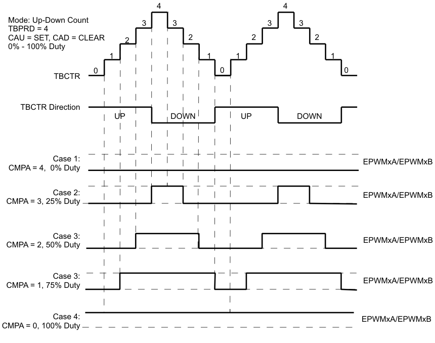 Figure 14-25 Up-Down Count Mode
Symmetrical Waveform
Figure 14-25 Up-Down Count Mode
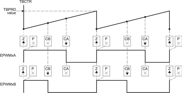
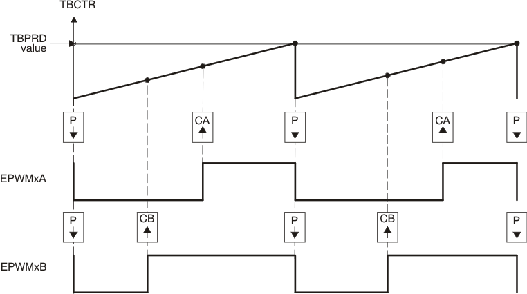
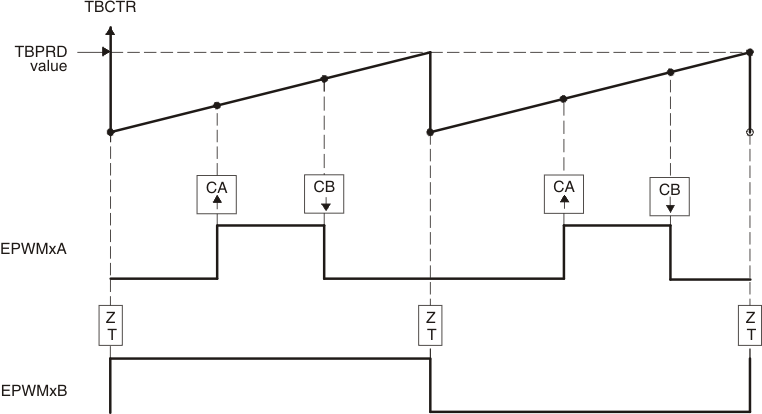
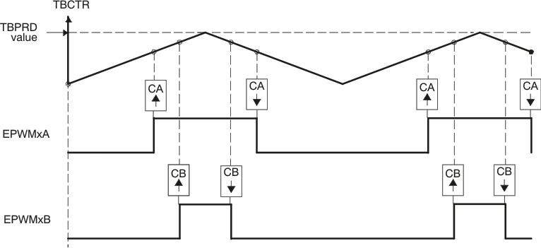
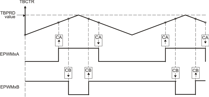
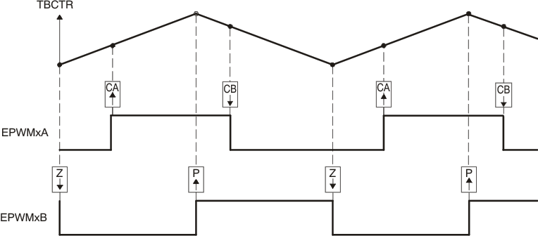
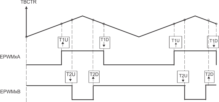
Symmetrical WaveformThe PWM waveforms in Figure 14-26 through Figure 14-31 show some common action-qualifier configurations. Some conventions used in the figures and examples are as follows:
- TBPRD, CMPA, and CMPB refer to the value written in the respective registers. The active register, not the shadow register, is used by the hardware.
- CMPx, refers to either CMPA or CMPB.
- EPWMxA and EPWMxB refer to the output signals from ePWMx
- Up-Down means count-up-and count-down mode, Up means up-count mode and Down means down-count mode
- Sym = Symmetric, Asym = Asymmetric
