SPRUHW1A June 2014 – October 2021 TMS320F28052-Q1 , TMS320F28052M , TMS320F28052M-Q1 , TMS320F28054-Q1 , TMS320F28054M , TMS320F28054M-Q1
- 1Read This First
- 1 F2805xM InstaSPIN-MOTION Enabled MCUs
- 2InstaSPIN-MOTION Key Capabilities and Benefits
- 3InstaSPIN-MOTION Block Diagrams
- 4Application Examples
- 5Evaluating InstaSPIN-MOTION Performance
- 6Microcontroller Resources
6.2 Memory Utilization
Table 7-2 lists the memory usage for each SpinTAC component. In SpinTAC Plan, there are a large number of configuration functions.
| Component | Code (.text) (16-bit Words) | RAM (.ebss) (16-bit Words) |
|---|---|---|
| Velocity Control | 0x2E6 | 0x4C |
| Velocity Move | 0x488 | 0x5C |
| Velocity Plan (Minimum) | 0x666 | 0x4E |
| Velocity Plan (Maximum) | 0x14BA | 0x4E |
| Velocity Identify | 0x392 | 0x3C |
| Position Converter | 0x21C | 0x4C |
| Position Control | 0x416 | 0x62 |
| Position Move | 0x13A4 | 0xCC |
| Position Plan (Minimum) | 0x7AE | 0x60 |
| Position Plan (Maximum) | 0x16F4 | 0x60 |
Table 7-3 breaks down the maximum stack utilization of SpinTAC components when run individually. The stack consumption of InstaSPIN-FOC is included. To calculate the stack usage, the entire memory section where the stack is placed is filled with known values. The corresponding code was then run for a few minutes. The memory area where the stack was allocated was analyzed and the amount of used memory was calculated.
| Configuration | Maximum Stack Used (16-bit Words) |
|---|---|
| Velocity Control | 0x0120 |
| Velocity Move | 0x0120 |
| Velocity Plan + Move + Control | 0x0120 |
| Velocity Identify | 0x0120 |
| Position Converter | 0x0120 |
| Position Control | 0x0120 |
| Position Move | 0x0120 |
| Position Plan + Move + Control | 0x0120 |
Table 7-4 shows the allocated memory for the InstaSPIN-FOC and SpinTAC library.
| Features | 2806xF | 2806xM | 2805xF | 2805xM | 2802xF |
|---|---|---|---|---|---|
| FAST | Yes | Yes | Yes | Yes | Yes |
| SpinTAC | No | Yes | No | Yes | No |
| Maximum Number of Motors that can be controlled | 2 | 2 | 2 | 2 | 1 |
| Relocalable Controller Structure | No | No | Yes | Yes | Yes |
| FAST Version | 1.6 | 1.6 | 1.7 | 1.7 | 1.7 |
| Public Library needs to be added to project | No | No | No | No | Yes |
| ROM Library [size, hex, words] | 4000 | 4000 | 3D27 | 3D27 | 2000 |
| ROM Library Start [address, hex] | 3F 8000 | 3F 8000 | 3F 8808 | 3F 8808 | 3F C000 |
| Library Required RAM [size, hex, words] | 800 | 800 | 800 | 800 | 200 |
| Library Start RAM [address, hex] | 01 3800 | 01 3800 | 00 8000 | 00 8000 | 00 0600 |
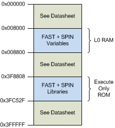
For the F2805xM device, FAST v1.7 and SpinTAC v2.2.7 are stored in execute-only memory. Figure 7-2 shows the memory map for these devices, highlighting locations that have been assigned for FAST and SpinTAC.
 Figure 6-2 F2805xF and F2805xM Allocated Memory for InstaSPIN-FOC and SpinTAC Library
This variant of the library requires the addition of a control structure to the project, which will be loaded to user's RAM space. The control structure is public and contains no specific information about the estimator, but it is needed to allow the library interface to work. The control structure can be declared as a single item, or can be declared as an array of two for user's controlling two motors independently.
// control structure declaration in main.c to control one motor
CTRL_Obj ctrl;
// control structure declaration in main.c to control two motors
CTRL_Obj ctrl[2];
Each ctrl member consumes 0x100 x 16-bit words, or 512 Bytes of memory. The specific location of ctrl or ctrl[2] structures is not important, so users can store these structures anywhere in volatile memory.