SPRUIF3B May 2017 – March 2019 DRA790 , DRA791 , DRA793 , DRA797
-
DRA79x EVM CPU board
- Trademarks
- 1 Introduction
- 2 Overview
- 3
Hardware
- 3.1 Hardware Architecture
- 3.2 DRA71x, DRA79x, TDA2E-17, and AM570x Processor
- 3.3 Power Architecture
- 3.4 Reset Structure
- 3.5 Clocks
- 3.6
Memory
- 3.6.1 SDRAM Memory
- 3.6.2 QSPI Flash Memory
- 3.6.3 EMMC Flash Memory
- 3.6.4 MicroSD Card Cage
- 3.6.5 GPMC NOR Flash Memory
- 3.6.6 GPMC NAND Flash Memory
- 3.6.7 Boot Modes
- 3.6.8 JTAG/Emulator and Trace
- 3.6.9 UART Terminal
- 3.6.10 DCAN and CAN Interfaces
- 3.6.11 Universal Serial Bus (USB)
- 3.6.12 Wired Ethernet
- 3.6.13 Video Output
- 3.6.14 Video Input
- 3.6.15 Mini-PCIe
- 3.6.16 Media Local Bus (MLB)
- 3.6.17 Audio
- 3.6.18 COM8 Module Interface
- 3.6.19 eFuse Programming Supply
- 3.6.20 User Interface LEDs
- 3.6.21 Power Monitoring
- 3.6.22 I2C Peripheral Map
- 3.6.23 GPIO List
- 3.6.24 I/O Expander List
- 3.6.25 Configuration EEPROM
- 4
Signal Multiplex Logic
- 4.1 GPMC and QSPI Selection (MUX A)
- 4.2 GPMC, VIN1, and VOUT3 Selection (MUX B)
- 4.3 GPMC and EMMC Selection (MUX C)
- 4.4 VIN2A and EMU Selection (MUX D, MUX E)
- 4.5 VIN2A and RGMII1 Selection (MUX F)
- 4.6 RGMII0 and VIN1B Selection (MUX J)
- 4.7 SPI2 and UART3 Selection (MUX K)
- 4.8 DCAN2 and I2C3 Selection (MUX L)
- 5 USB3 Supported Configurations
- 6 References
- Revision History
3.3 Power Architecture
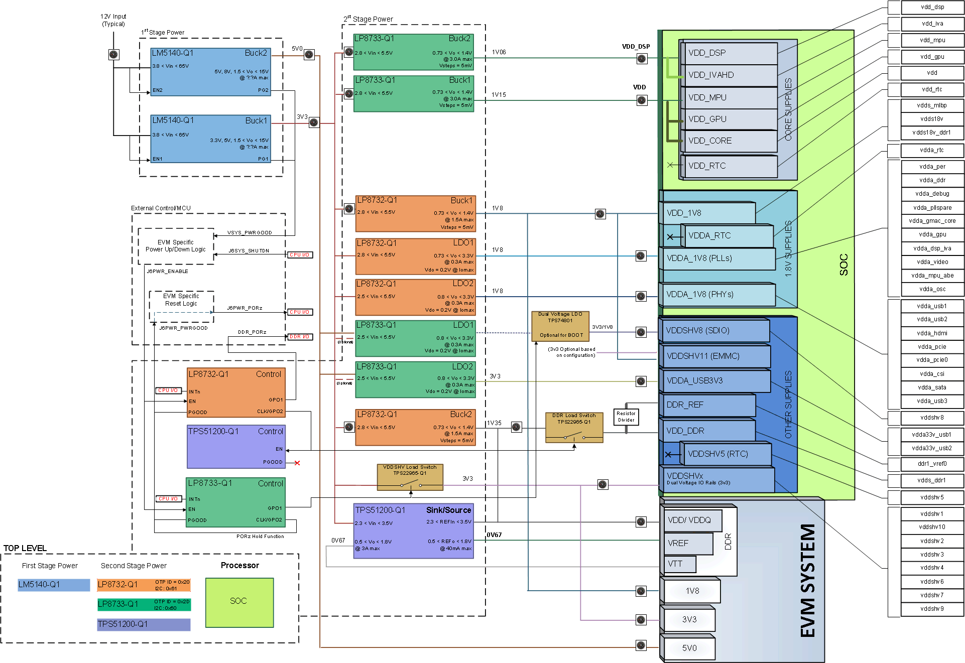
Figure 6 shows the power distribution system of the EVM. The power-management solution is created from four total devices (see Figure 6). A step-down 12 V to 3.3 V, 5-V converter provides the primary 3v3 and 5v0 power rails for the rest of the system. The LP8733 and LP8732 devices are optimized for the SoC power needs and sequence requirements. A sink/source regulator provides the DDR termination.
 Figure 6. Power Distribution Block Diagram
 An external power supply is required to power the EVM, but is not included as part of the EVM kit. The external power supply requirements follow:
- Power jack: 2.5-mm ID, 5.5-mm OD
- Nom voltage: 12 VDC
- Maximum current: 5000 mA
- Efficiency level V
External power supply regulatory compliance certifications: recommended selection and use of an external power supply which meets TI’s minimum electrical ratings requirement and complies with applicable regional product regulatory and safety certification requirements, such as UL, CSA, VDE, CCC, and PSE.
Table 4 lists the recommended and tested power supplies that can be used with the EVM.
Table 4. 12 V, 5A, 65W Compatible Wall Supplies
| Digi-Key Part Number | Manufacturer Part Number | Manufacturer | Output Connector | Notes |
|---|---|---|---|---|
| 102-3417-ND | SDI65--12-U-P5 | CUI Inc. | Barrel plug,
2.1 mm x 5.5 mm O.D. x 9.5 mm |
Required adapter, provided in the EVM kits |
| 62-1221-ND | KTPS65-1250DT-3P-
VI-C-P1 |
Volgen America/Kaga Electronics USA | Barrel plug,
2.1 mm x 5.5 mm O.D. x 9.5 mm |
Required adapter, provided in the EVM kits |
| 102-3419-ND | SDI65-12-UD-P6 | CUI Inc. | Barrel plug,
2.1 mm x 5.5 mm O.D. x 9.5 mm |
Required adapter, provided in the EVM kits |
| SDI65-12-U-P6-ND | SDI65-12-U-P6 | CUI Inc. | Barrel plug,
2.1 mm x 5.5 mm O.D. x 9.5 mm |
|
| SDI65-12-UD-P6-ND | SDI65-12-UD-P6 | CUI Inc. | Barrel plug,
2.1 mm x 5.5 mm O.D. x 9.5 mm |