SPRUIL2A February 2019 – September 2019 OMAP-L132 , OMAP-L138 , TMS320C6742 , TMS320C6746 , TMS320C6748
1.1 Features
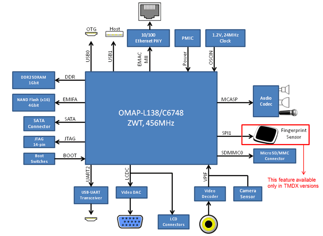
- TI TMS320C6748 DSP or OMAP-L138 Application Processor
- 456-MHz C674x Fixed/Floating Point DSP
- 456-MHz ARM926EJ RISC CPU (OMAP-L138 only)
- On-Chip RTC
- 128 MByte DDR2 SDRAM running at 150 MHz
- 128 MByte 16-bit wide NAND FLASH
- 1 Micro SD/MMC Slot
- One mini-USB Serial Port (on-board serial to USB)
- One Fast Ethernet Port (10/100 Mbps) with status LEDs
- One USB Host port (USB 1.1)
- One mini-USB on the go (OTG) port (USB 2.0)
- One SATA Port (3Gbps)
- One VGA Port (15 pin D-SUB)
- One LCD Port (Beagleboard XM connectors)
- One Composite Video Input (RCA Jack)
- One Leopard Imaging Camera Sensor Input (36-pin ZIP connector)
- Three AUDIO Ports (1 LINE IN and 1 LINE OUT and 1 MIC IN)
- 14-pin JTAG header (No onboard emulator; external emulator is required)
 Figure 1. LCDK Block Diagram
 NOTE
- The LCDK does not have an onboard emulator. An external emulator from TI or a third-party will be required.
- The LCD port connector was designed to support an off-the-shelf LCD panel that is no longer available from any vendor. We are not aware of any other off the shelf LCD panel that will work with LCDK. You need to create your own adapter board in order to evaluate an LCD panel using the LCDK board.