SPRUIQ5 May 2019 TMS320F280021 , TMS320F280021-Q1 , TMS320F280023 , TMS320F280023-Q1 , TMS320F280023C , TMS320F280025 , TMS320F280025-Q1 , TMS320F280025C , TMS320F280025C-Q1 , TMS320F280040-Q1 , TMS320F280040C-Q1 , TMS320F280041 , TMS320F280041-Q1 , TMS320F280041C , TMS320F280041C-Q1 , TMS320F280045 , TMS320F280048-Q1 , TMS320F280048C-Q1 , TMS320F280049 , TMS320F280049-Q1 , TMS320F280049C , TMS320F280049C-Q1 , TMS320F28374D , TMS320F28374S , TMS320F28375D , TMS320F28375S , TMS320F28375S-Q1 , TMS320F28376D , TMS320F28376S , TMS320F28377D , TMS320F28377D-EP , TMS320F28377D-Q1 , TMS320F28377S , TMS320F28377S-Q1 , TMS320F28378D , TMS320F28378S , TMS320F28379D , TMS320F28379D-Q1 , TMS320F28379S
2.1 Bringing Up the Board
The experiment uses a separate control power supply for the CPU and interface circuits and another control power supply for inverter gate drive circuits. For more information, see entry 2 of the Power Supply Connection Configuration table in the DesignDRIVE IDDK Hardware Reference Guide.
For setting up the experimental hardware, perform the following steps:
- Populate jumpers [Main]-J3, [Main]-J4, and [Main]-J5 in front of macro M3.
- Mount jumpers [Main]-J6, [Main]-J7 and [Main]-J8 in front of macro M9 and resistors [Main]-R9, [Main]-R11 and [Main]-R13 and GND plane resistor R15 (on the bottom side). For more information, see the Various GND Planes on the Bottom Side of Board and Default Connection of Various GND Planes figures in the DesignDRIVE IDDK Hardware Reference Guide.
- Ensure that resistors [Main]-R8, [Main]-R10 and [Main]-R12 are not populated.
- Unpack the TMDXCNCD28379D control card.
- Slide the card into the connector slot of [Main]-H1. (Push down using even pressure on both ends of the card until it cannot slide further. To remove the card, spread open the retaining clips and pull the card out, applying even force at the edges.)
- Connect a USB cable to connector J1 on the control card. (The control card isolates the JTAG signals between the C2000 device and the computer. LED D2 on the control card should light.)
- Ensure that toggle switch [M9]-SW1 is in Int position.
- Connect an isolated 15-V DC-power supply to [M9]-JP1.
- Turn on toggle switch [M9]-SW1.
- Ensure that toggle switch [M3]-SW1 is in the Int position.
- Connect an isolated 15-V DC-power supply to [M3]-JP1.
- Turn on toggle switch [M3]-SW1. ([M3]-LD1 should turn on.)
- Apply the DC-bus power only when the guide instructs. Two options exist to get DC-bus power:
- To use an external, variable DC-power supply, do the following:
- Set the power-supply output to zero.
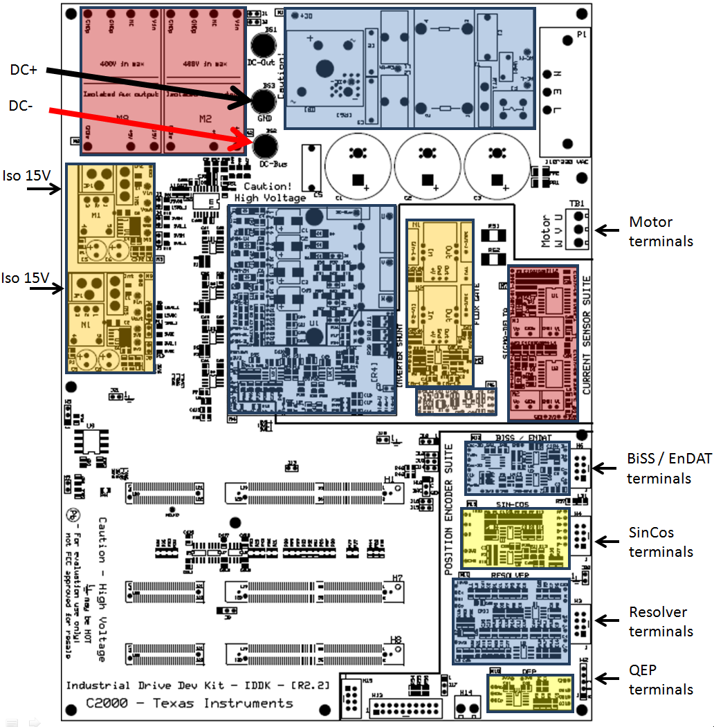
- Connect [Main]-BS2 and [Main]-BS3 to the + and – terminals of the DC-power supply, respectively. (See Figure 2-1.)
- To use AC-Mains power, do the following:
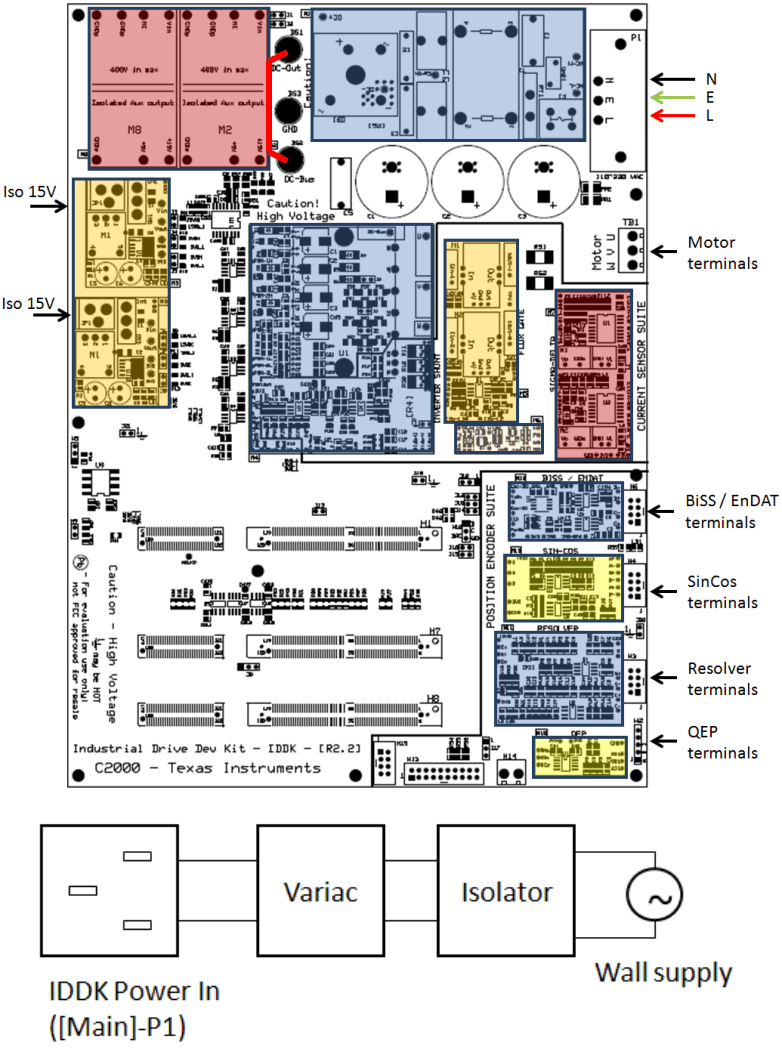
- Connect [Main]-BS1 to [Main]-BS2 using a banana plug cord.
- Connect the end of the AC-power cord to [Main]-P1.
- Set the output of the variac to zero.
- Connect the variac to the wall supply through an isolator. (See Figure 2-2.)
- Connect the other end fo the AC-power cord to the output of the variac.
- To use an external, variable DC-power supply, do the following:
NOTE
More LEDs on the control card light up indicating that the control card is receiving power from the board.
NOTE
Connect the motor to the [Main]-TB1 terminals only after finishing the first incremental build.
WARNING
DC-bus capacitors remain charged long after the mains supply is disconnected. Use caution.
 Figure 2-1 Connection Diagram With External Variable DC-Power Supply Providing DC-Bus Voltage
  Figure 2-2 Connection Diagram With AC Input