SPRUIT0A December 2019 – May 2020
-
Jacinto7 EVM Infotainment Expansion
- Trademarks
- 1 Introduction
- 2 Infotainment Expansion Board Overview
- 3 Infotainment Expansion Board - User Setup/Configuration
- 4
Infotainment Expansion Board Hardware Architecture
- 4.1 Infotainment Expansion Board Hardware Top Level Diagram
- 4.2 Expansion Connectors
- 4.3 Board ID EEPROM
- 4.4 Audio Codec Interface
- 4.5 FPD link De-Serializer Interface (Audio)
- 4.6 DIR Interface
- 4.7 DIT Interface
- 4.8 Legacy Audio/JAMR3 Connectors
- 4.9 VIN/VOUT Mux Selection
- 4.10 HDMI Interface Bridge
- 4.11 FPD Link Display Serializer Interface
- 4.12 Parallel Camera Interface
- A Jacinto7 EVM Interface/IO Mapping
- Revision History
4.5 FPD link De-Serializer Interface (Audio)
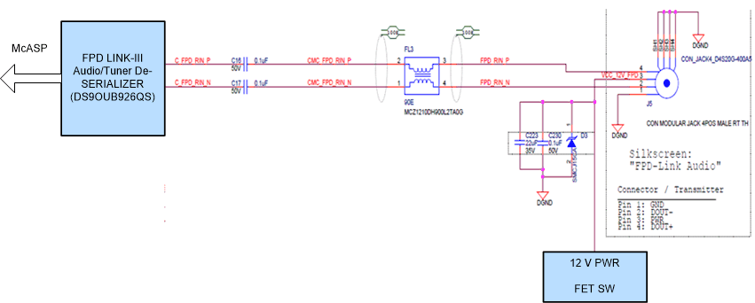
Infotainment expansion board uses FPD link III De-serializer IC Mfr. Part# DS90UB926QSQE for recover the audio signals from the FPD-Link interface. The de-serializer recovers up to eight digital audio channels, frame sync plus I2S channel across digital link. HSD connector Mfr. Part# D4S20G-400A5-C is used to receive the input signal.
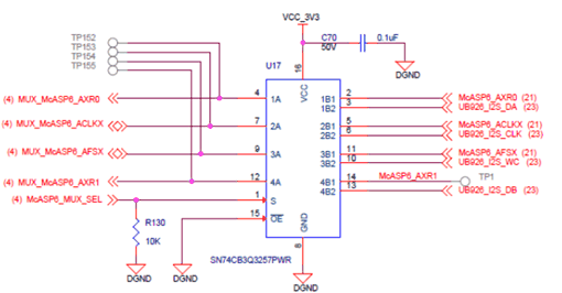
The recovered eight audio data signal and AFSX connected directly to McASP port of J7 SoC through CP board B-B connector. And I2S signals from de-serializer are connected to McASP port of J7 SoC through DIR/FPDLink MUX selection IC(U17) on Infotainment board. For MUX channel selection through GPIO Expander, see Section A.2.
 Figure 11. DIR/FPDLink Mux Selection
 The I2C signals from SOC being used for controlling/configuring of the de-serializer and remote device. A 57.6KΩ Pull up and 121K Ω pull down is provided on ID[X] pin to set the 7‘b I2C address to 0x3B.
The default mode set for the de-serializer is mode0. For the resistor population option to set different modes, see Figure 12.
Power +12 V is provided to the HSD connector using a power switch TPS1H100AQPWPRQ1 to power an external board. By default, power switch is OFF and it can be enabled by a GPIO expander signal (PWR_SW_UB926).
 Figure 12. FPD Link De-Serializer Interface